Two point latching system
a latching system and two-point technology, applied in the field of latches, can solve the problems of unreliable latching operation, two-point latching and button failure to make one piece,
- Summary
- Abstract
- Description
- Claims
- Application Information
AI Technical Summary
Benefits of technology
Problems solved by technology
Method used
Image
Examples
second embodiment
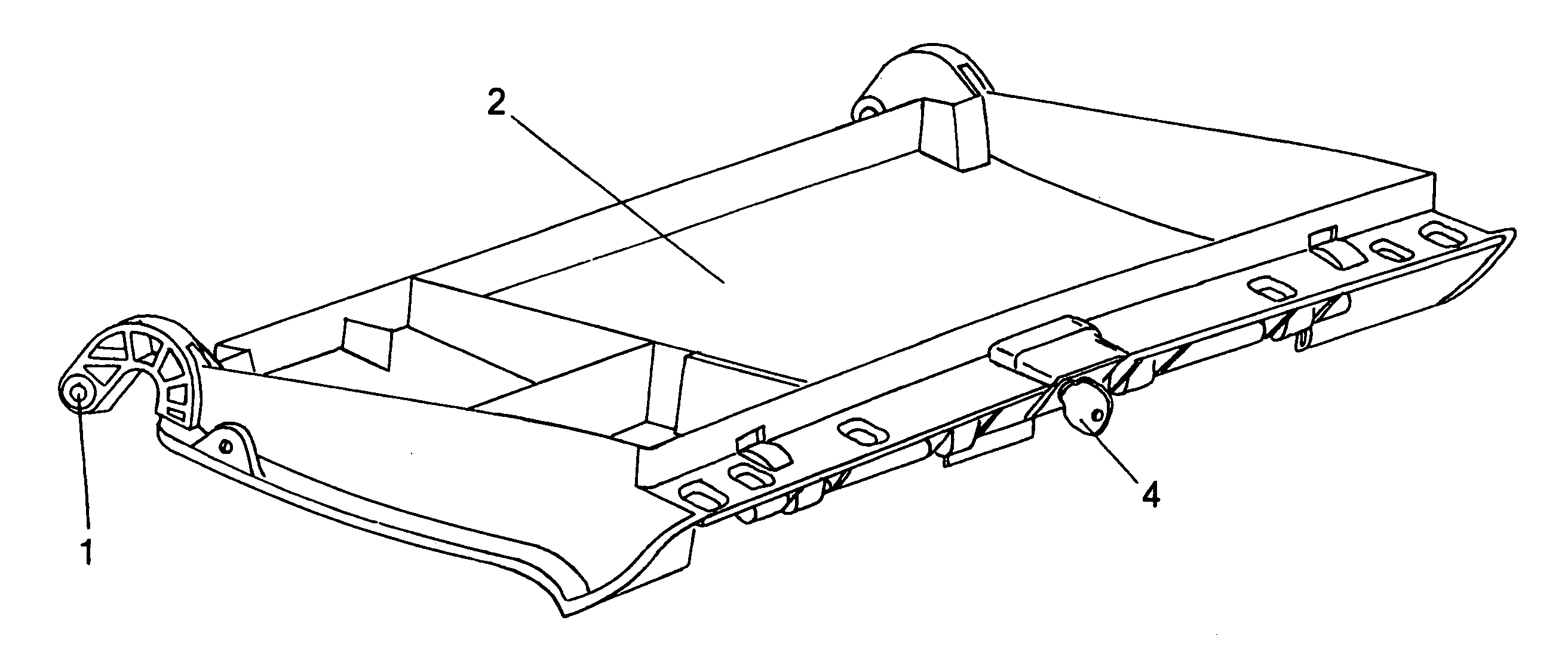
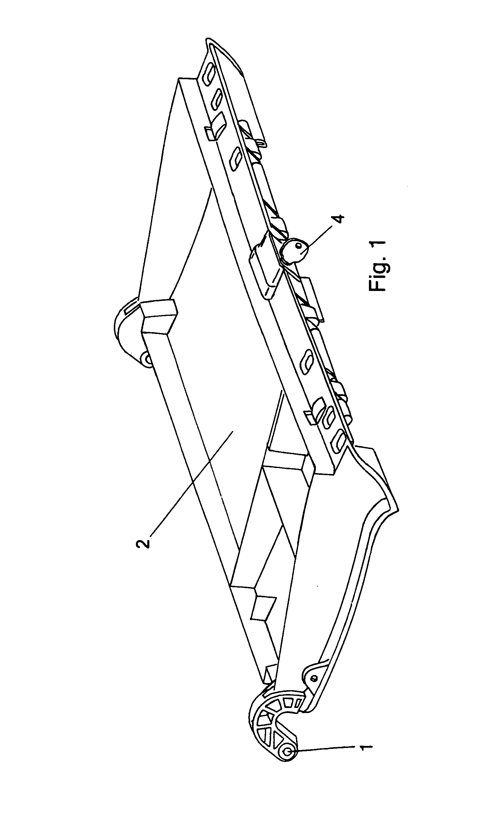
[0061]the button pawl shaft of the present invention is shown in FIG. 14. Two pawls 108 are at the ends of the button pawl shaft 109. A precompressed torsion spring (not shown) presses against each of bezels 107 which is fixed to a lower structure (not shown) which the user intends to fasten to an upper structure (not shown). A key 104 shown in FIG. 18 can be fitted into a lockplug 115 which in turn is located in a button 106. The button 106 is part of the button pawl shaft 109. Also shown in FIG. 14 is a left shaft piece 111, a center shaft piece 112, and a right shaft piece 113.
[0062]FIG. 15 is a perspective view of the center shaft piece 112 of the button pawl shaft 109 of FIG. 14. Recesses 116 are shown at opposite ends of center shaft piece 112. Button 106 is also shown and rotates the button pawl shaft 109 when a user presses on the button 106 when the button 106 is not placed in a locked position by lockplug 105.
[0063]FIG. 16 shows left shaft piece 111 having pawl 108 and pro...
first embodiment
[0065]FIGS. 20 and 24 show a torsion spring 100 which can be of plastic or metal. As shown, the windings of torsion spring 100 has a U-shape at each end. Torsion spring 100 is shown placed and retained in spring pocket 118 where it is precompressed as in FIG. 25. In the present invention, a bezel 107 is shown in FIG. 19 wherein the bezel 107 has a snap fitting tongue 117. As shown in FIG. 25, bezel 107 and snap fitting tongue 117 on the bezel are shown prior to being placed on the axis 119 of button pawl shaft 109. Axis 119 has a flat portion 120 which provides a second snap position at a predetermined angle which thereby preloads the spring at the required position. The flat portions 120 assist the assembler of the button pawl shaft in placing the bezel 107 on the axis 119 of the shaft in a desired position. Bezel 107 is shown placed on the axis 119 as shown in FIG. 29. FIGS. 27 and 28 show the bezel 107 in intermediate positions as the bezel 107 rotates around the axis 119 of the ...
third embodiment
[0066]In FIG. 30 a bezel of the present invention is shown in a two piece configuration. The bezel 107 is provided with an aperture 121. In this embodiment, rather than being snap fit onto the axis 119 of the button pawl shaft 109, the bezel 107 can be clamped onto the axis when in combination with bottom piece 122.
PUM
 Abstract
Description
Claims
Application Information
 - R&D
- Intellectual Property
- Life Sciences
- Materials
- Tech Scout
- Unparalleled Data Quality
- Higher Quality Content
- 60% Fewer Hallucinations
Browse by: Latest US Patents, China's latest patents, Technical Efficacy Thesaurus, Application Domain, Technology Topic, Popular Technical Reports.
© 2025 PatSnap. All rights reserved.Legal|Privacy policy|Modern Slavery Act Transparency Statement|Sitemap|About US| Contact US: help@patsnap.com


