Cap frame and cap-frame setting frame
a technology of cap frame and setting frame, which is applied in the direction of embroidering machine, automatic machine, textiles and paper, etc., can solve the problems of not being able to easily align the center of the cap frame, so as to achieve easy and surely alignment
- Summary
- Abstract
- Description
- Claims
- Application Information
AI Technical Summary
Benefits of technology
Problems solved by technology
Method used
Image
Examples
first embodiment
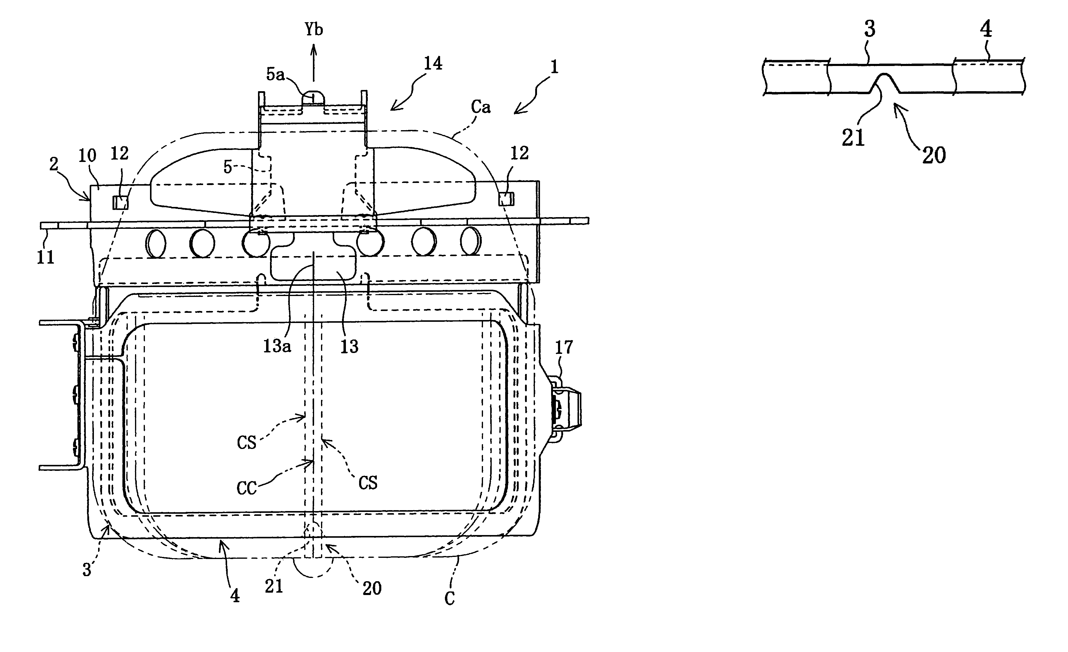
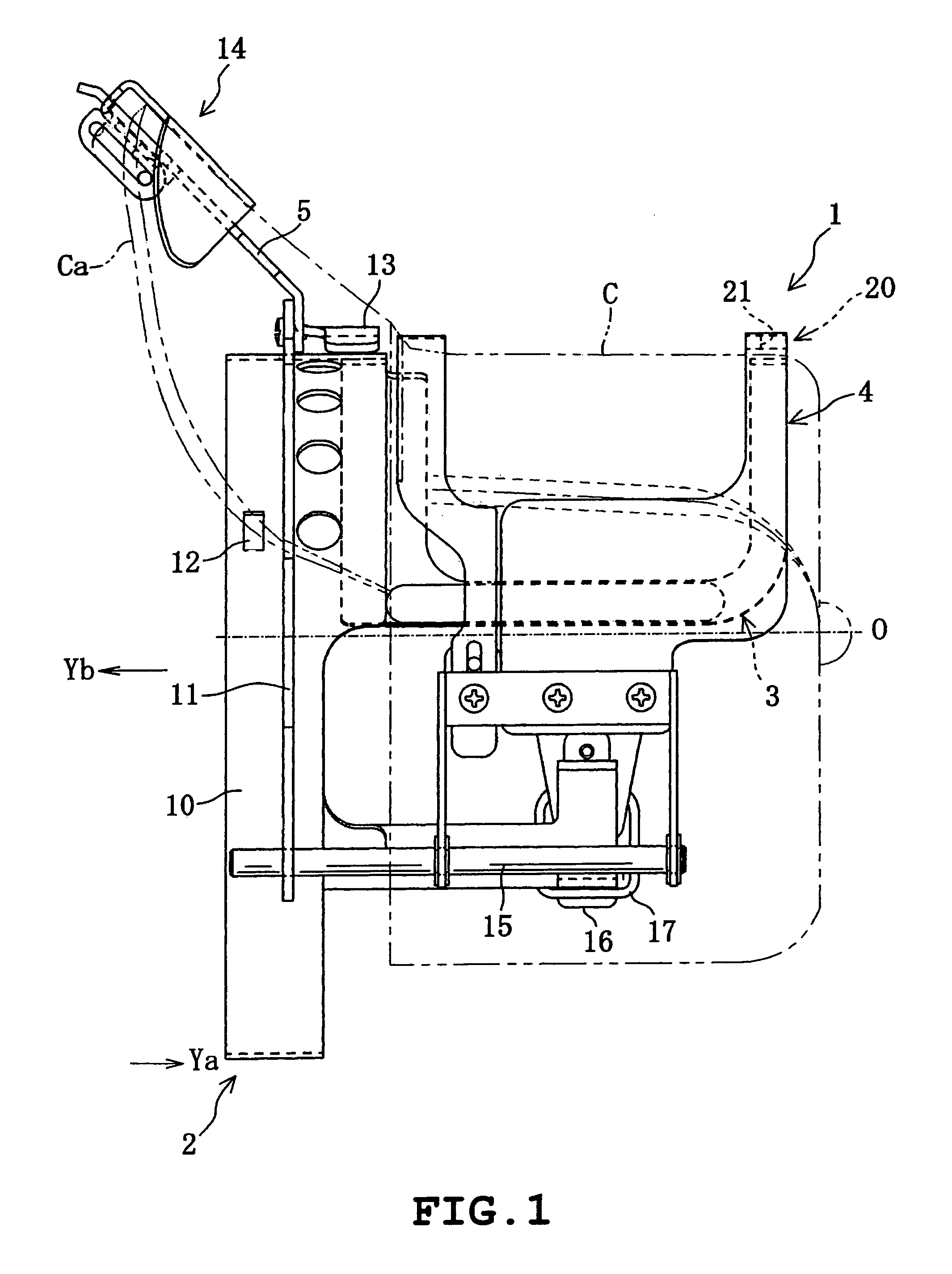
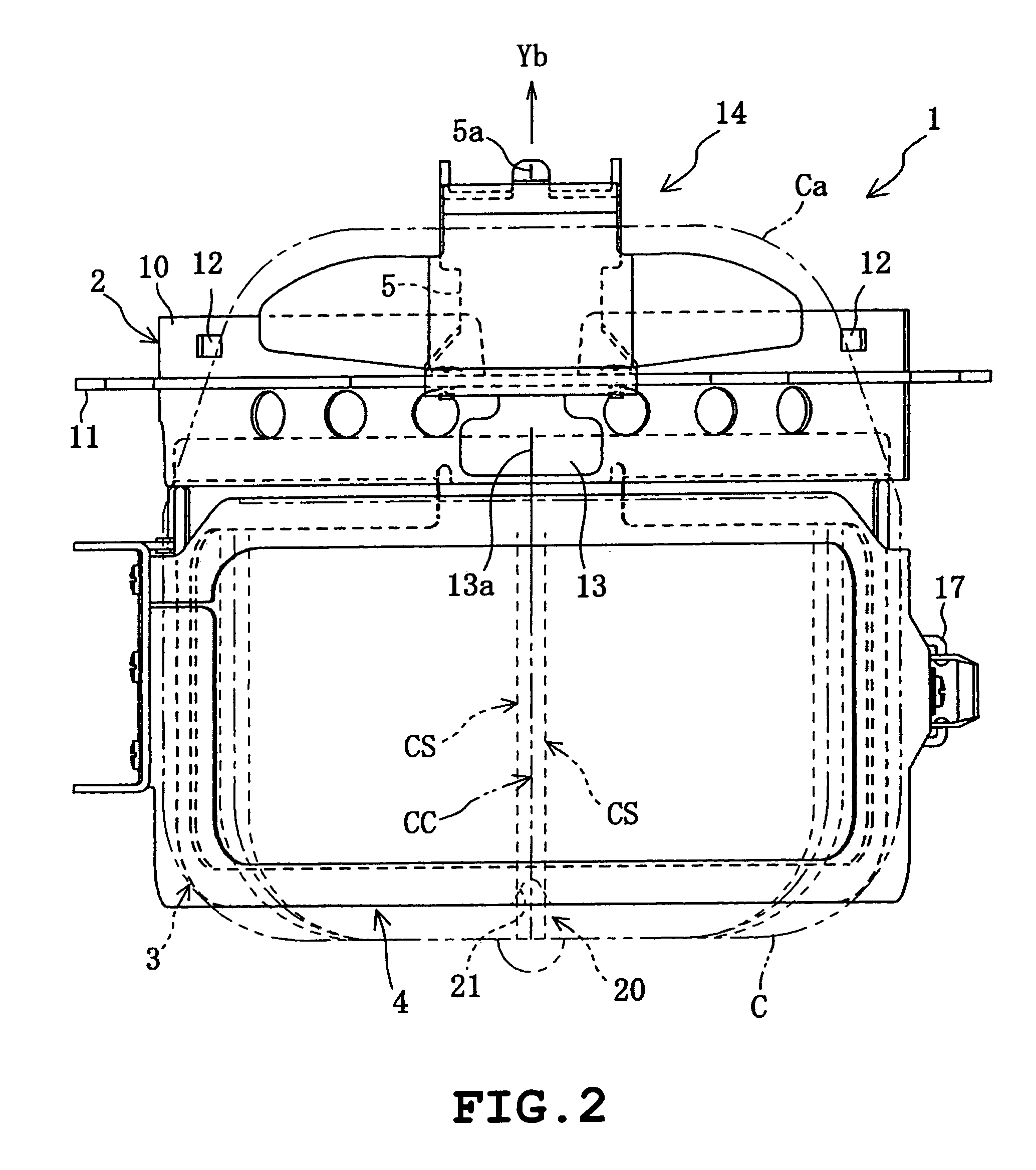
[0041]Now referring to FIGS. 1 to 8, an explanation will be given of this invention. In this embodiment, this invention is applied to an industrial multi-head embroidery sewing machine capable of simultaneously doing embroidery for plural caps. In this embodiment, it is assumed that the embroidery is done on the front of a baseball cap C. Incidentally, in following explanation, as seen from FIG. 8, it is assumed that the direction in which an operator sits for the multi-head sewing machine is a front direction; the front-rear direction is a Y direction and the left-right direction is an X direction. In FIG. 1, the direction of arrow Ya is the front direction, and in FIGS. 1, 2 and others, the direction of Yb is the rear direction from which a cap frame is mounted (or fit).
[0042]First, referring to FIG. 8, an explanation will be given of the configuration of a body of a multi-head sewing machine M. The body of the multi-head sewing machine M includes an embroidery-machine base frame ...
third embodiment
[0078]Next referring to FIGS. 11 to 14, an explanation will be given of this invention. In this embodiment, this invention is applied to a cap-frame setting frame 30 with a cap frame 60 for holding the cap C being detachably attached. In this embodiment, the cap frame 60 is a cap frame of “non-frame” type. Incidentally, in the following description, it is assumed that the direction indicated by arrow Ya in FIG. 11 is a forward direction, and others.
[0079]As seen from FIGS. 11 to 14, the cap-frame setting frame 30 according to the invention includes a base frame 31 to which a cap frame body 61 of the cap frame 60 is attached in its positioned status, a fixing mechanism 40 provided at the rear end of the base frame 31 for fixing the cap-frame setting frame 30 to the working table 9, etc.
[0080]The fixing mechanism 40 includes an attaching member 40 having a ⊃-shape when viewed from the side, a screw member 42 screw-engaged to pass through a screw hole of the lower part of the attaching...
PUM
 Abstract
Description
Claims
Application Information
 - R&D
- Intellectual Property
- Life Sciences
- Materials
- Tech Scout
- Unparalleled Data Quality
- Higher Quality Content
- 60% Fewer Hallucinations
Browse by: Latest US Patents, China's latest patents, Technical Efficacy Thesaurus, Application Domain, Technology Topic, Popular Technical Reports.
© 2025 PatSnap. All rights reserved.Legal|Privacy policy|Modern Slavery Act Transparency Statement|Sitemap|About US| Contact US: help@patsnap.com


