D-ring with universal movement and bolt

a technology of d-rings and seat belts, applied in the direction of safety belts, pedestrian/occupant safety arrangements, vehicular safety arrangements, etc., can solve the problems of increased vehicle restraint system cost, increased vehicle safety costs, and increased safety hazards, so as to reduce the binding of seat belts, reduce the effect of rattling and eliminating rattling

Inactive Publication Date: 2006-07-25
KEY SAFETY SYST
View PDF5 Cites 29 Cited by
  • Summary
  • Abstract
  • Description
  • Claims
  • Application Information

AI Technical Summary

Benefits of technology

[0006]The present invention comprises a novel vehicle restraint system and seatbelt support. The inventive vehicle restraint system has a unique D-ring located at the shoulder anchor point. In contrast to existing D-rings, the inventive D-ring has a pivot connection that permits the D-ring to pivot about the anchoring point, allowing the D-ring to move with the seatbelt. To reduce rattle, the pivot connection has a curved surface on which the D-ring may move relative to its anchoring support. In this way, the D-ring is retained securely on its support to eliminate rattling while still reducing binding of the seatbelt.
[0007]The pivot connection may comprise a curved surface that allows movement of the D-ring in a direction transverse to an axis of rotation of the D-ring. The curved surface may mate with another curved surface to improve the fit between the D-ring and the anchor support. These curved surfaces permit smooth movement of the D-ring relative to the support.
[0008]To further reduce rattling of the D-ring, a spring may extend between the D-ring and the vehicle body to buffer vibrations from the vehicle body. In addition, washers may retain the web guide on the support as well as provide a location for the curved surfaces. A polymer, such as nylon, may be used for these surfaces to further reduce rattle. A gap may exist between the support and the web guide to increase the level of movement between the support and the D-ring.

Problems solved by technology

The D-ring may cause binding of the seatbelt, reducing the ease of extension and retraction of the seatbelt relative to the seatbelt retractor.
These additional mechanisms introduce significant expense to the overall cost of the vehicle restraint system.
Applicant has discovered that the binding of the seatbelt results from an inability of the D-ring to move freely with the shoulder belt portion of the seatbelt.
This feature, however, has a drawback.
This rattling of a safety component of the vehicle is unpleasant as well as potentially disconcerting to the vehicle occupant.

Method used


Image

  • D-ring with universal movement and bolt
  • D-ring with universal movement and bolt
  • D-ring with universal movement and bolt

Examples


Embodiment Construction

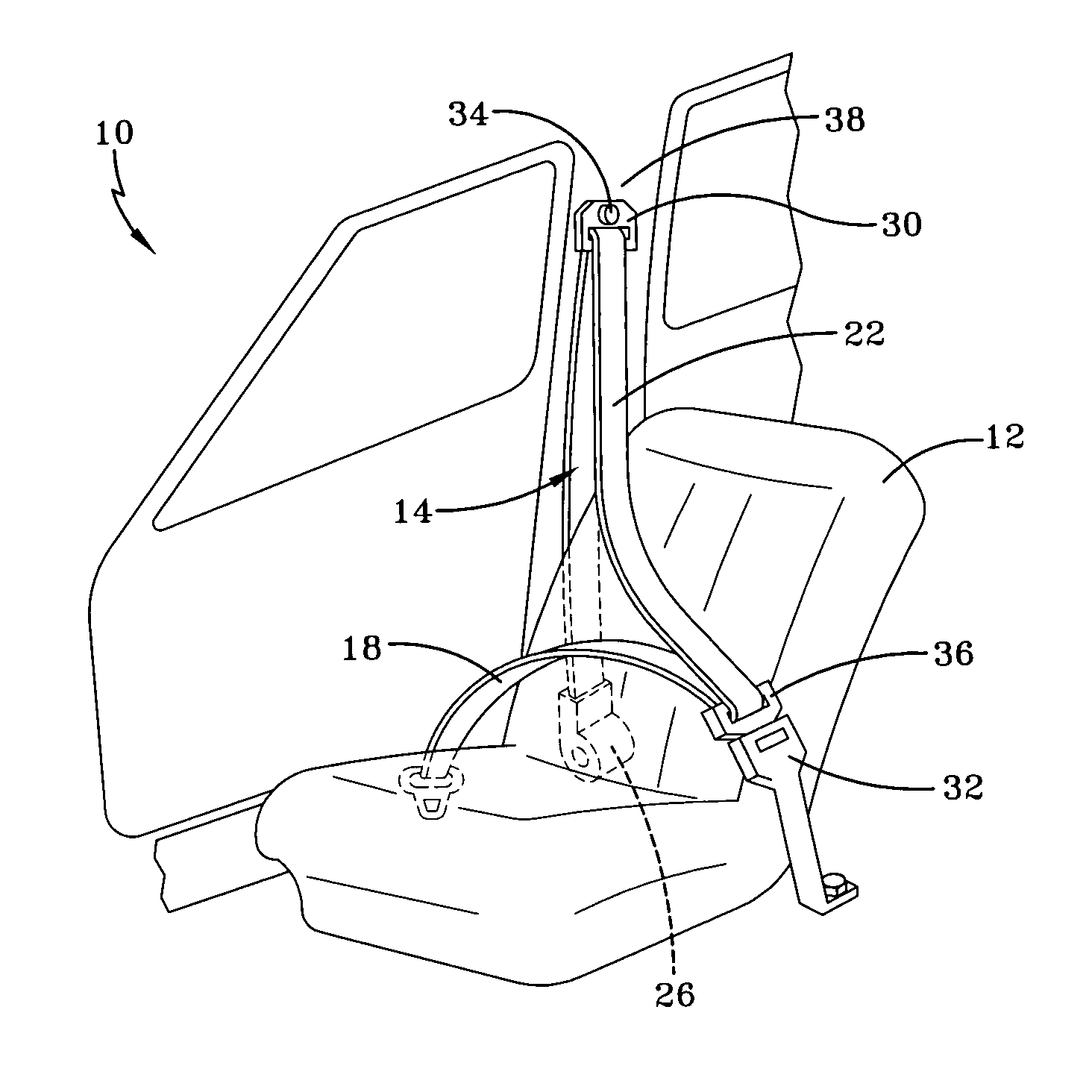
[0019]FIG. 1 illustrates a view of inventive vehicle restraint system 10 for seat 12. As shown, vehicle restraint system 10 comprises seat belt web 14 anchored to vehicle body 38. As known, seat belt web 14 has lap belt portion 18 and shoulder belt portion 22. Lap belt portion 18 is anchored to vehicle body 38 and loops through tongue 36, which selectively clips into buckle 32. From tongue 36, seatbelt web 14 extends across an anticipated shoulder and chest location of a vehicle occupant to form shoulder belt portion 22. Shoulder belt portion 22 loops through web guide 30, here a D-ring, and down toward seat belt retractor 26. These elements of vehicle restraint system 10 are known.

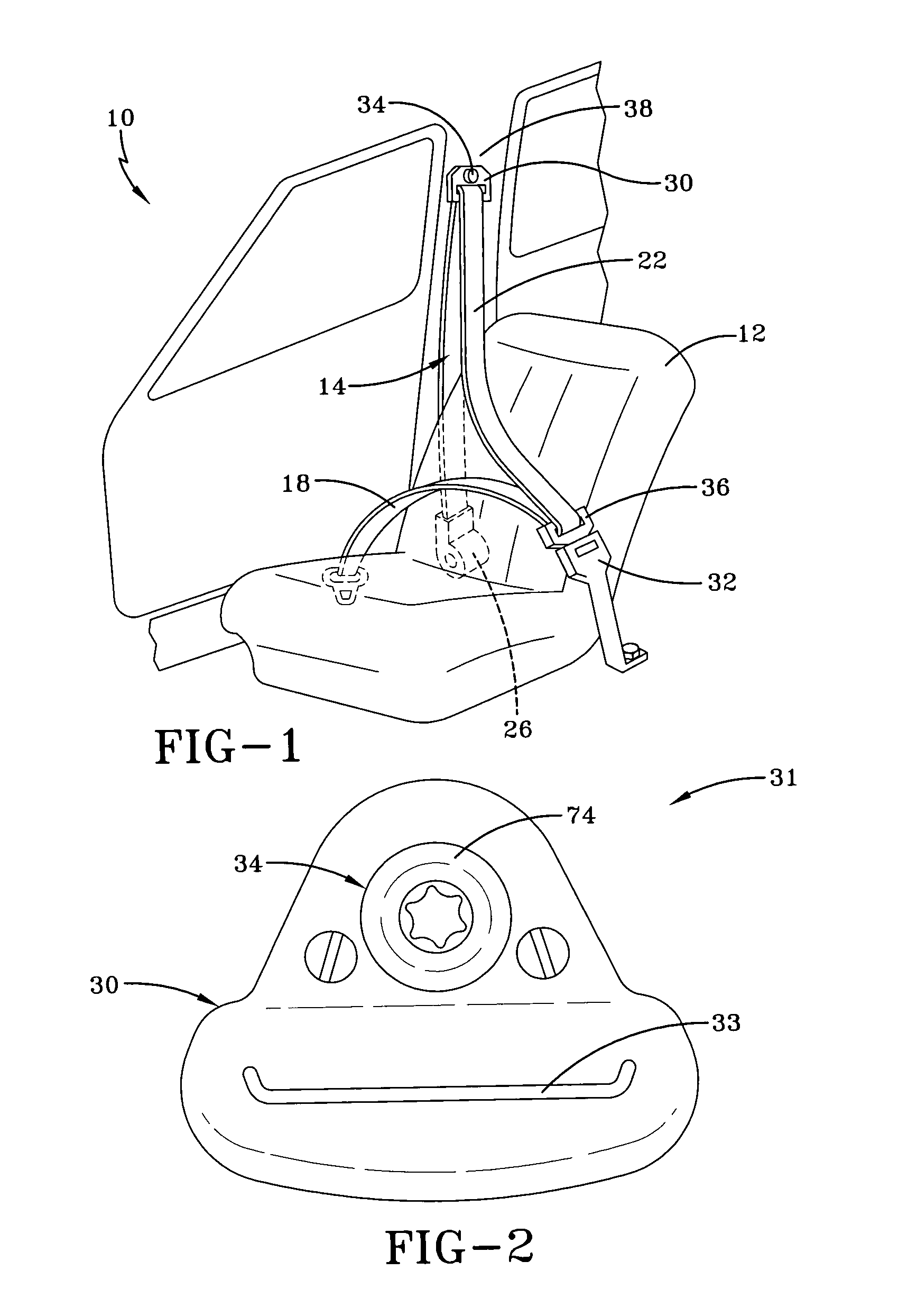
[0020]In contrast to existing vehicle restraint systems, inventive vehicle restraint system 10 has a novel web guide 30. As shown in FIG. 2, web guide 30 comprises a D-ring having slot 33 to receive a loop of seatbelt web 14. Web guide 30 is anchored to vehicle body 38 as shown in FIG. 1 by support 34, he...


PUM


Abstract

A web guide assembly has a D-ring to receive a seatbelt. The D-ring is attached to a support by a joint. The joint allows universal movement relative to the support. The web guide assembly may be part of a vehicle restraint system.

Description

BACKGROUND OF THE INVENTION[0001]This invention relates to a D-ring for a seatbelt.[0002]A vehicle restraint system typically comprises a seatbelt anchored at various points to a vehicle body. The seatbelt or seatbelt web may have both a lap belt portion and a shoulder belt portion and may retract into a seatbelt retractor that takes up the slack of the seatbelt. The seatbelt has an anchoring point on the vehicle body above the anticipated height of a shoulder of a seated vehicle occupant. The anchoring point serves to support the shoulder belt portion of the seatbelt across the vehicle occupant. At this anchoring point, the seatbelt extends from the seatbelt retractor through a support loop, known as a D-ring, anchored above the seated vehicle occupant. The D-ring acts as a web guide for the seatbelt web and typically has a slot to receive the seat belt web.[0003]The D-ring may cause binding of the seatbelt, reducing the ease of extension and retraction of the seatbelt relative to ...

Claims


Application Information

Patent Timeline
Patent Type & Authority Patents(United States)
IPC IPC(8): B60R22/00B60R22/18B60R22/24
CPCB60R22/24B60R2022/1837
Inventor DESMARAIS, ROBERT J.ARNOLD, SR., DAVIDTEMPLE, BAYARD
Owner KEY SAFETY SYST
Why Eureka
Try Eureka