Flexible seat frame

a seat frame and flexible technology, applied in the field of seat frames, can solve the problem that the type of seat frame does not optimize the energy management of the sea

Inactive Publication Date: 2006-07-25
BE AEROSPACE INCORPORATED
View PDF8 Cites 14 Cited by
  • Summary
  • Abstract
  • Description
  • Claims
  • Application Information

AI Technical Summary

Problems solved by technology

This type of brace does not optimize energy management within the seat, particularly in the case of a divan seat.

Method used


Image

  • Flexible seat frame
  • Flexible seat frame
  • Flexible seat frame

Examples


Embodiment Construction

[0019]As a preview to understanding the invention, it is useful to review some of the forces acting on an aircraft during takeoff and landing. During the takeoff roll, various forces act on the aircraft. These forces included the thrust (T) which is produced by the aircraft's power plant. In addition to thrust, lift (L) and drag (D) are produced as soon as the airplane has speed depending on the angle of attack and dynamic pressure. Rolling friction (F) results when there is a normal force on the wheels and is the product of the normal force and the coefficient of the rolling friction. The normal force pressing the wheels against the runway surface is the net of weight and lift while the rolling friction coefficient is a function of the tire type and runway surface texture.

[0020]The acceleration of the airplane at any instant during takeoff roll is a function of the net accelerating force and the airplane mass. Thus, from Newton's second law of motion:

a=Fn / M

or

a=g(Fn / W)

where: a=acce...


PUM


Abstract

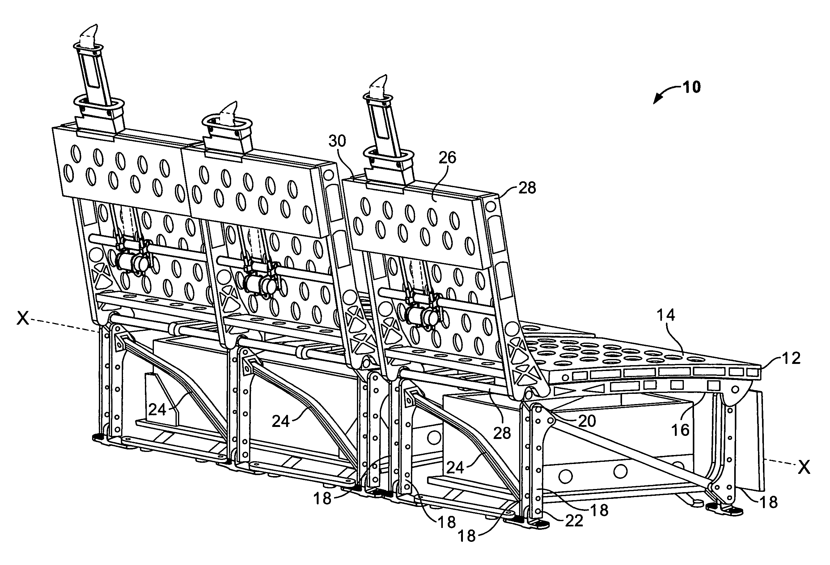
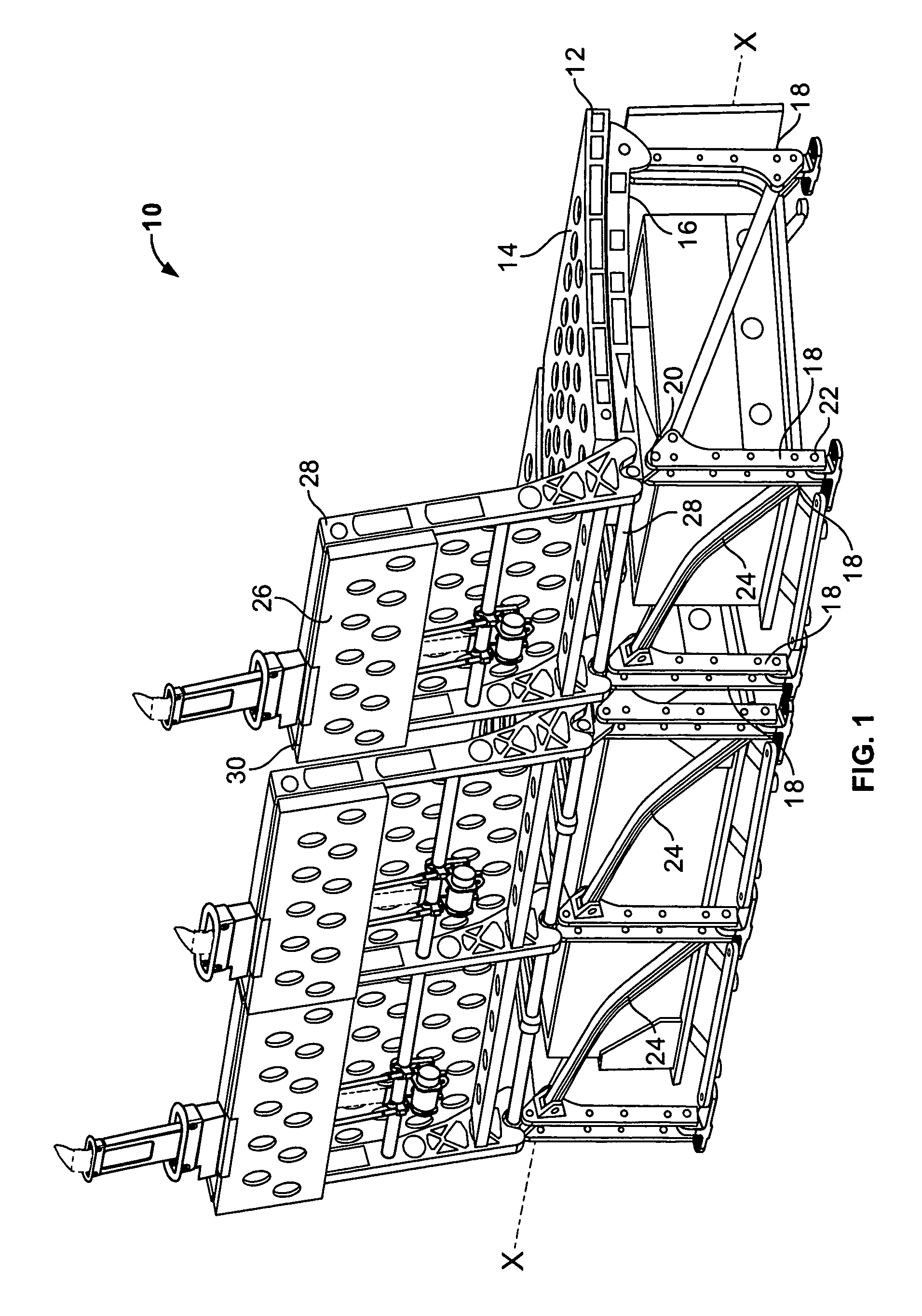
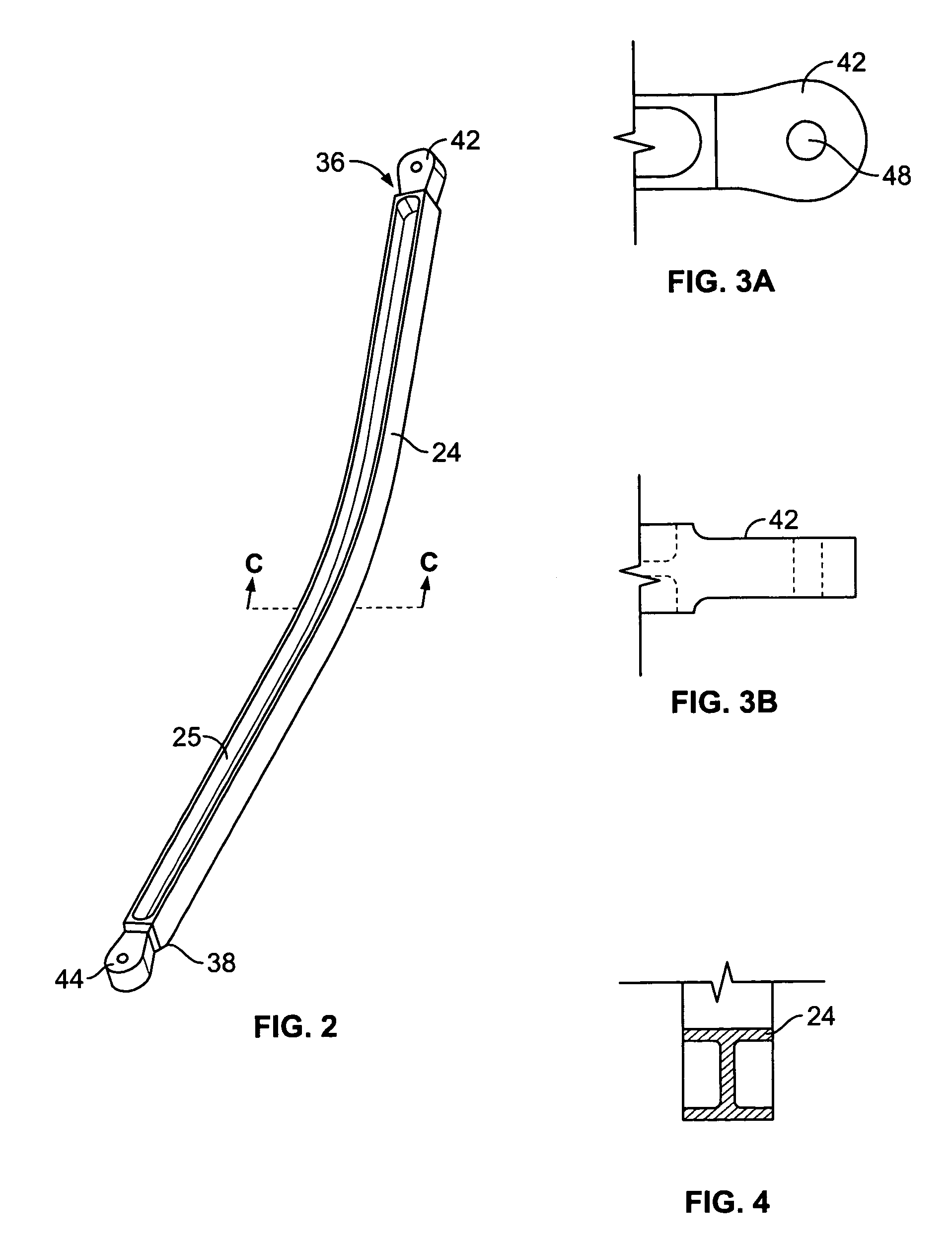
A support frame for a seat, in particular an aircraft seat, where the support frame includes a seat support member having an upper surface and a lower surface, a plurality of leg members that each have a first end and a second end, with the first end attached to the lower surface of the seat support member. An angled flexible leg brace capable of stretching to absorb a dynamic load on the frame extends between at least two of the plurality of leg members.

Description

CROSS-REFERENCE TO RELATED PATENT APPLICATIONS[0001]Related subject matter is disclosed in copending U.S. patent application Ser. No. 10 / 944,134, filed Sep. 17, 2004, entitled A CURVED PROFILE TRACKING PLATFORM FOR A PASSENGER SEAT; U.S. patent application Ser. No. 10 / 944,488, filed Sep. 17, 2004, entitled INDEPENDENT DIVAN DOOR AND DRAWER ASSEMBLY; U.S. patent application Ser. No. 10 / 944,487, filed Sep. 17, 2004, entitled ATTACHMENT ASSEMBLY FOR MOUNTING A SEAT TO THE FLOOR OF A VEHICLE; and U.S. patent application Ser. No. 10 / 943,672, filed Sep. 17, 2004, entitled ADJUSTABLE SEAT BELT GUIDE ASSEMBLY.FIELD OF THE INVENTION[0002]This invention pertains to a seat frame, and, more particularly, to an aircraft passenger seat frame.BACKGROUND OF THE INVENTION[0003]In order for aircraft seating to be certified for use in an aircraft, the seat must pass a series of performance tests to ensure that it will withstand the various dynamic forces that it may be subjected to, particularly in an...

Claims


Application Information

Patent Timeline
Patent Type & Authority Patents(United States)
IPC IPC(8): B60N2/42
CPCB64D11/0619B64D11/06
Inventor WILLIAMSON, JOHNGAIKWAD, PAWAN
Owner BE AEROSPACE INCORPORATED
Why Eureka
Try Eureka