Sports racket having a uniform string structure

a string structure and tennis racket technology, applied in the field of tennis rackets, can solve the problems of unmarketable and unusable, unsatisfactory ball rebound speed, and likely not being able to achieve the desired ball trajectory,

Inactive Publication Date: 2006-07-25
BRANDT RICHARD A
View PDF23 Cites 16 Cited by
  • Summary
  • Abstract
  • Description
  • Claims
  • Application Information

AI Technical Summary

Benefits of technology

[0010]It is an object of the present invention to provide an improved racket.
[0011]It is a further object of the present invention to provide a novel design for a racket, which has a sweet spot that is considerably larger than that of conventional rackets, so that the racket responds with the maximum possible degree of uniformity when a ball is struck almost anywhere on the racket face.
[0012]It is a further object of the present invention to provide a novel design for a racket, having a larger face area than conventional rackets, in order to produce more hits and better hits.

Problems solved by technology

If the impact location on a conventional racket is not on the sweet spot, or off-center, the ball encounters strings of different length and the resultant ball trajectory is probably not going to be the desired one.
Errors such as hits into the net, beyond the baseline, or too near the opponent, will often result.
Additionally, with a conventional racket, when a ball strikes parallel strings of equal tension but of different lengths, the strings vibrate with different frequencies, so that the combined effect produces a less-than-optimal ball rebound speed.
Further, although the Woehrle et al. patent suggested making the racket strings of equal length in the area of the sweet spot at least, a greater section of the racket face, such consideration was not reduced to practice, but was rejected as unmarketable and unusable.
The Woehrle et al. patent stated that “no practical way of achieving this end has been found.
Although these developments led to further enhanced performance, the lack of serious computer modeling, as well as the lack of interesting new ideas, have impeded significant progress.

Method used


Image

  • Sports racket having a uniform string structure
  • Sports racket having a uniform string structure
  • Sports racket having a uniform string structure

Examples


Embodiment Construction

[0041]The sports racket having a uniform string structure of the present invention will be described in the context of a preferred embodiment, namely a tennis racket. The novel aspects of the tennis racket described herein are applicable to other sports such as racquetball and squash. Accordingly, all such sports rackets incorporating the novel elements of the present invention are considered as within the scope of the present invention.

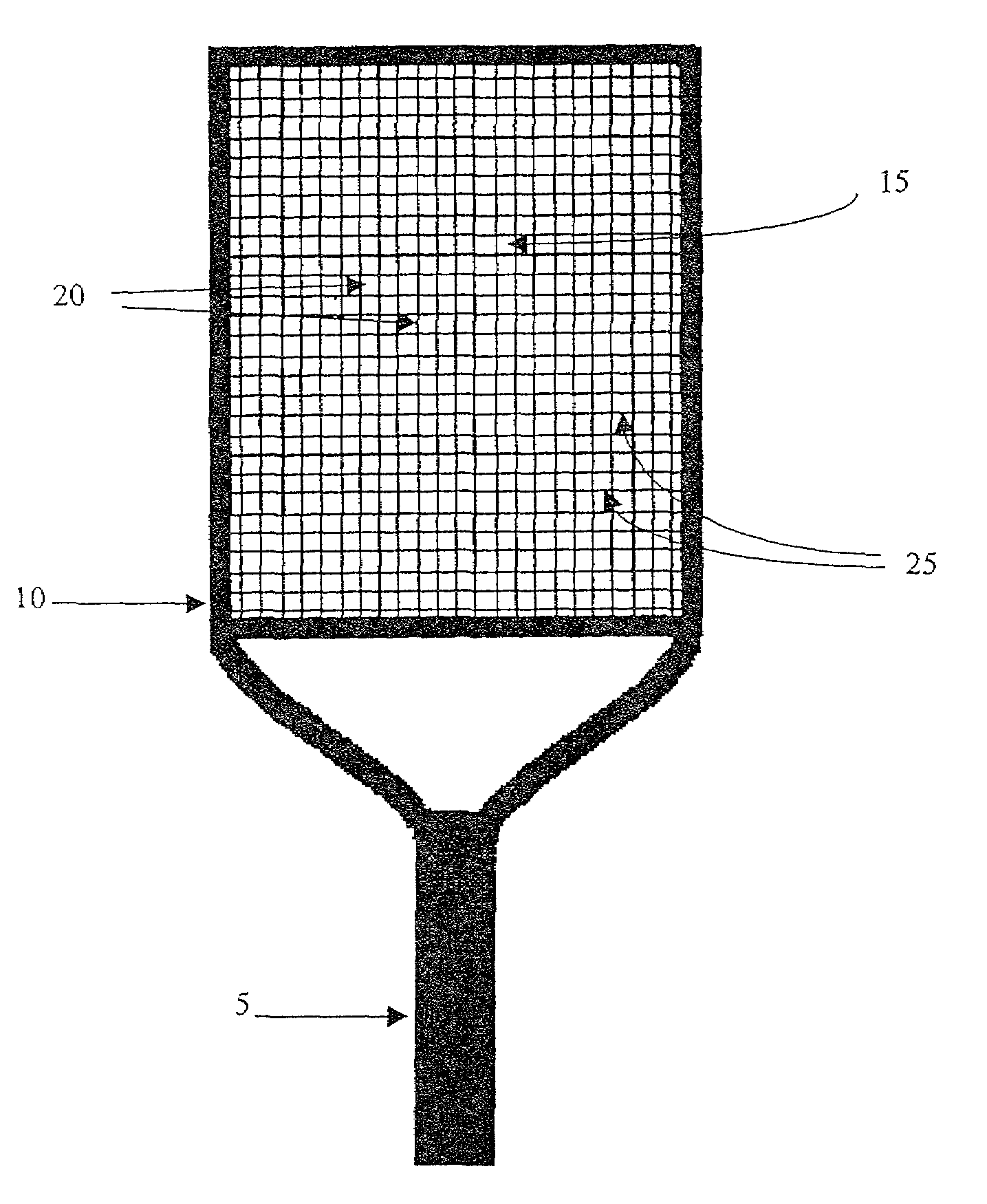
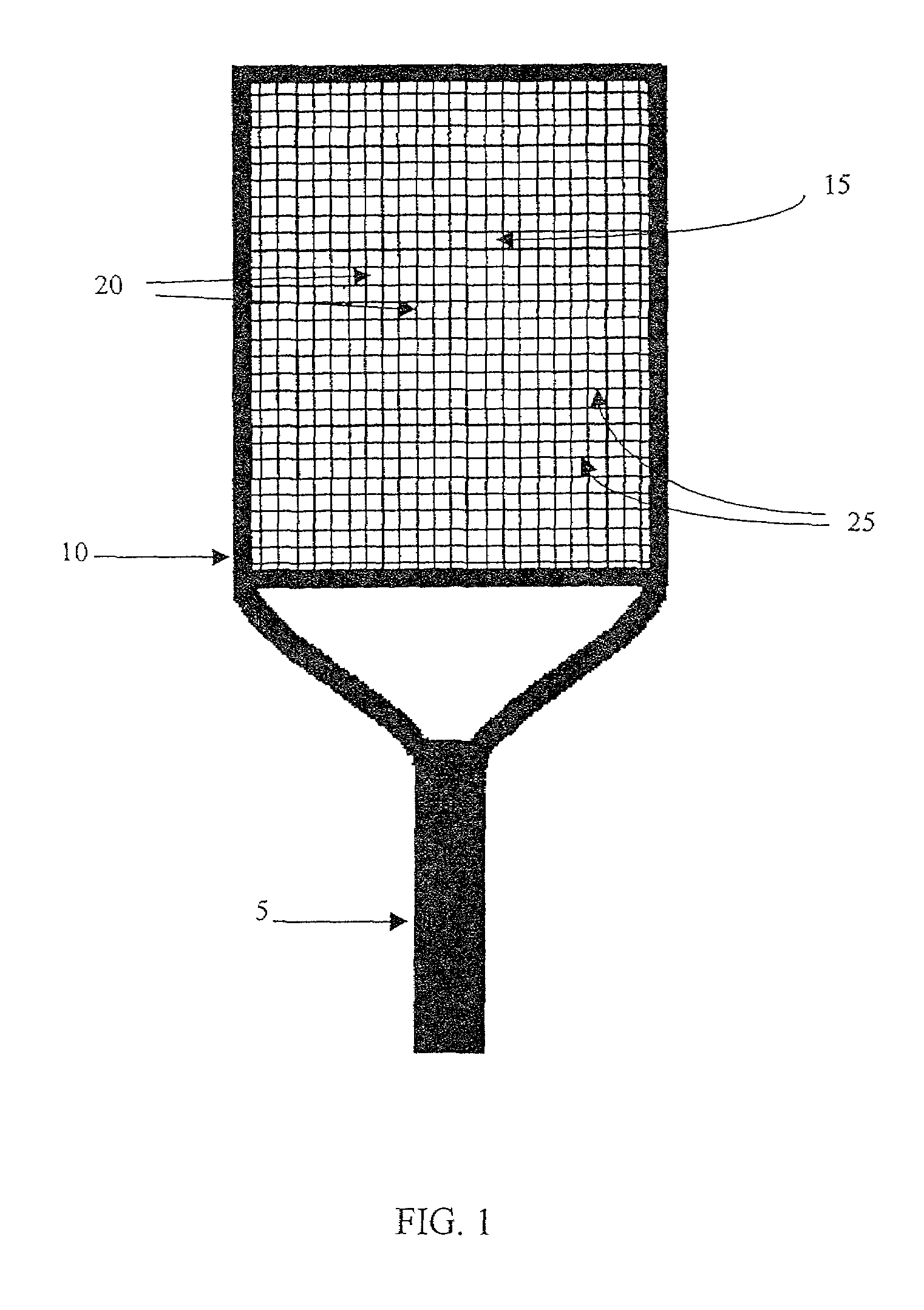
[0042]As seen in FIG. 1, the sports racket includes a handle 5 and a head 10 having a racket face 15 with transversal strings 25 and longitudinal strings 20.

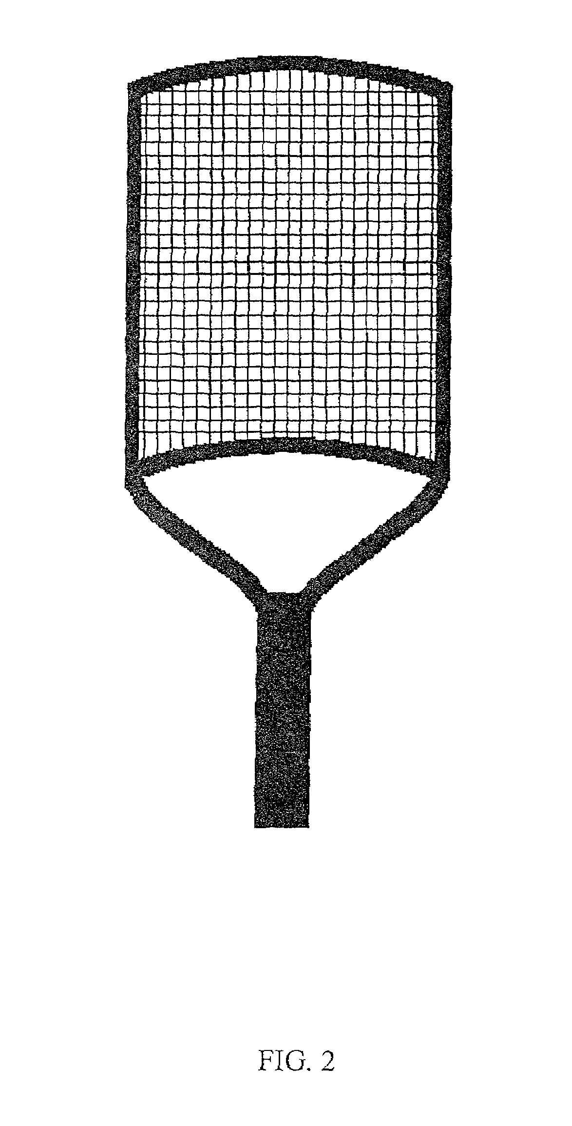
[0043]As illustrated in FIG. 1, in one preferred embodiment of the present invention, the racket face 15 has a rectangular shape with opposite sides being parallel and equal in length. The width of the racket face 15 is chosen to be 12″, the length of the racket face 15 is 14.5″, and the length of the handle 5 is 8″, so that the overall length of the racket is 28″. As seen in FIGS. 2, 3 and 4, th...


PUM


Abstract

A sports racket, for tennis and the like sports, has an elongated handle attached to a head having a racket face, which is spanned by a uniform string structure. The head has four sides, forming a non-elliptical shape, in which the opposite sides are substantially parallel. Longitudinal strings, all of which are substantially identical in length and run essentially parallel to each other, and transversal strings, all of which are substantially identical in length and run essentially parallel to each other and perpendicular to the longitudinal axis, span the racket face. The racket has a larger racket face than conventional rackets, while maintaining the length and weight measurements of conventional rackets, resulting in a very large sweet spot and more good hits. The racket has maximally long strings at all points on the racket face and strings substantially identical in length at all points on the racket face resulting in a uniformity of response for off-center hits, an increase in the ball rebound speed, a decrease in angular deflection for off-center hits, and the ability to set the tension of the strings such that they vibrate with the same frequency. The racket has a greater moment of inertia than conventional rackets, resulting in reduced racket rotation and a reduction of injuries to players, such as “tennis elbow”.

Description

[0001]This is a continuation of Ser. No. 09 / 715,762 filed Nov. 17, 2000 now U.S. Pat. No. 6,344,006.FIELD OF THE INVENTION[0002]The present invention relates to a sports racket. In the preferred embodiment, the present invention relates to a tennis racket having a uniform string structure such that all horizontal (transversal) strings are of equal length and all vertical (longitudinal) strings are of equal length.BACKGROUND OF THE INVENTION[0003]A range of tennis rackets exist which have been designed to provide a more uniform, powerful, forgiving and controlled response to all hits, and a larger optimal (“sweet spot”) area of the racket face.[0004]Typically, when a tennis player swings his racket to hit the ball, he assumes that the impact will be in the sweet spot of the racket face, and he swings accordingly. If the impact location on a conventional racket is not on the sweet spot, or off-center, the ball encounters strings of different length and the resultant ball trajectory is...

Claims


Application Information

Patent Timeline
Patent Type & Authority Patents(United States)
IPC IPC(8): A63B49/02
CPCA63B49/02A63B2049/0223A63B2049/0201A63B2049/0203A63B2049/0204A63B2049/0207A63B60/002
Inventor BRANDT, RICHARD A.
Owner BRANDT RICHARD A
Why Eureka
Try Eureka