
Super structure for roof patio solar plant

a solar plant and super structure technology, applied in the direction of heat collector mounting/support, batteries, lighting and heating equipment, etc., can solve the problems of no prior art illustration of a support frame structure, and achieve the effect of maximizing solar energy collection ability, collecting more solar energy, and maximizing solar energy collection ability

Inactive Publication Date: 2006-07-25
OAK EUGENE
View PDF26 Cites 8 Cited by
  • Summary
  • Abstract
  • Description
  • Claims
  • Application Information

AI Technical Summary

Benefits of technology

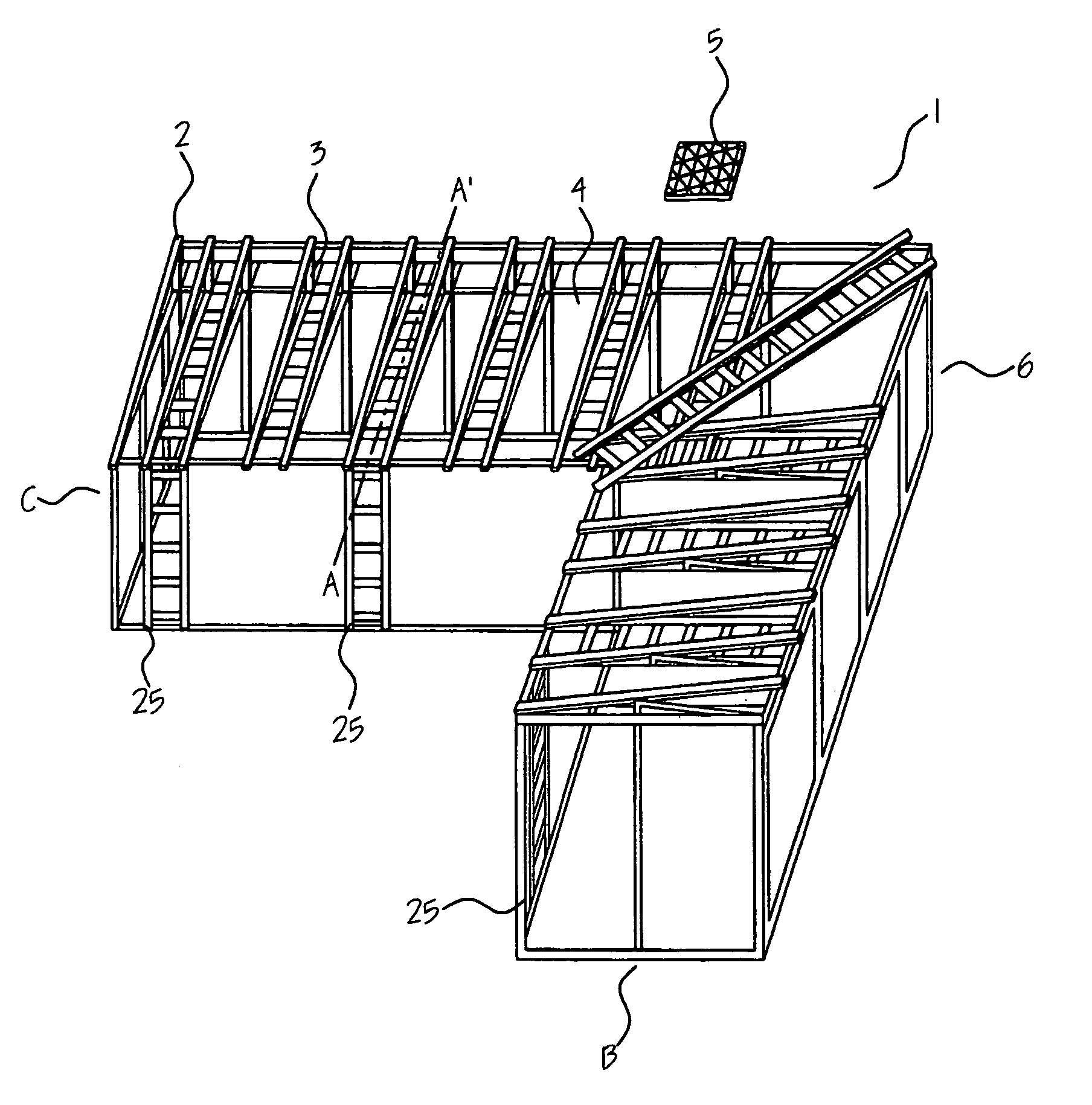
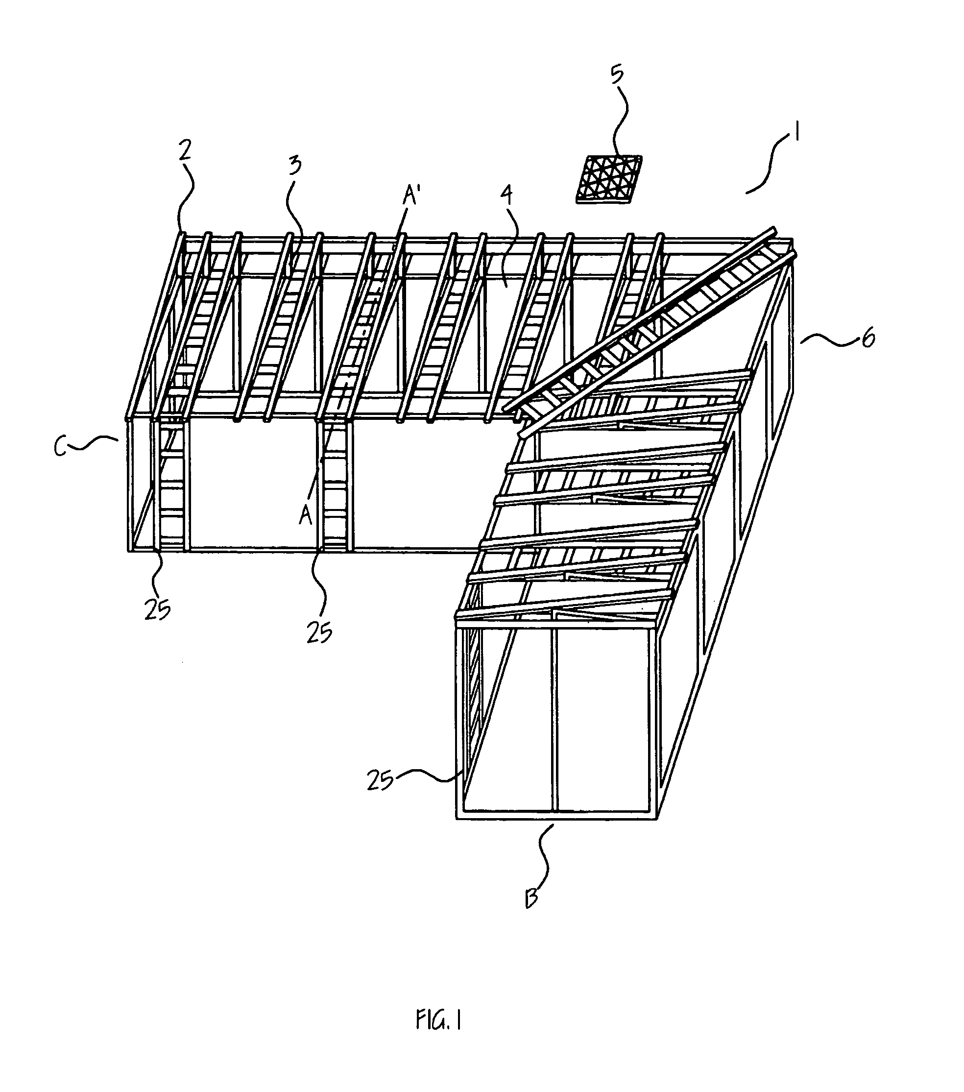
[0006]It is purpose of the current application to provide a supporting frame structure to render maximum solar energy collecting ability to solar cell modules, which are installed on a house roof. It is another purpose of the current application to provide environmentally affirmative views to the neighborhoods. The support frame structure is comprised of aluminum pipes, steel pipes, plastic plates, and woods. The frame structure has at least four vertical posts made of metal pipes, which are supporting other metal pipes, which constitute a planar frame for upper horizontal frame. A patio with a sloped top, at least 2 meter high, is developed between the roof of the house and the bottom of the top surface of the frame throughout the whole roof. This space is for install incidental facilities of the solar power systems such as pumps, batteries, and water tanks and for maintaining those facilities. As a result, the side view of the roof top frame structure, on which the solar cell panels are mounted, forms a rectangular triangle on a square. The angle between the sloped surface and the horizontal base is 3 to 75 degrees depend on the latitude of the geometric location of the place where the solar cell plate modules are installed. Maintenance accesses are developed between the solar cell module mounts. This maintenance access enables frequent cleaning and maintaining of the solar cell modules to maximize the solar energy collecting ability. The reinforced self-sustaining structure of the current application enables installing more solar cells on the roof and gathering more solar energy.

Problems solved by technology

None of the prior arts illustrate a support frame structure for mounting solar cell modules on a house roof with maximizing the collecting ability of the solar energy.

Method used


Image

  • Super structure for roof patio solar plant
  • Super structure for roof patio solar plant
  • Super structure for roof patio solar plant

Examples


Embodiment Construction

[0013]FIG. 1 is a perspective view of the solar cell module panel supporting frame structure (1) of the current application. The structure (1) is made of 5 cm by 5 cm (2 inch×2 inch) square carbon steel pipes (2) welded each other. Therefore, the structure (1) is self-sustaining. Upper face of the solar cell module panel supporting frame structure (1) is equipped with maintenance accesses (3) and solar cell module mounts (4). Solar cell module plates (5) of 180 cm by 76 cm are mounted on the mounts (4).

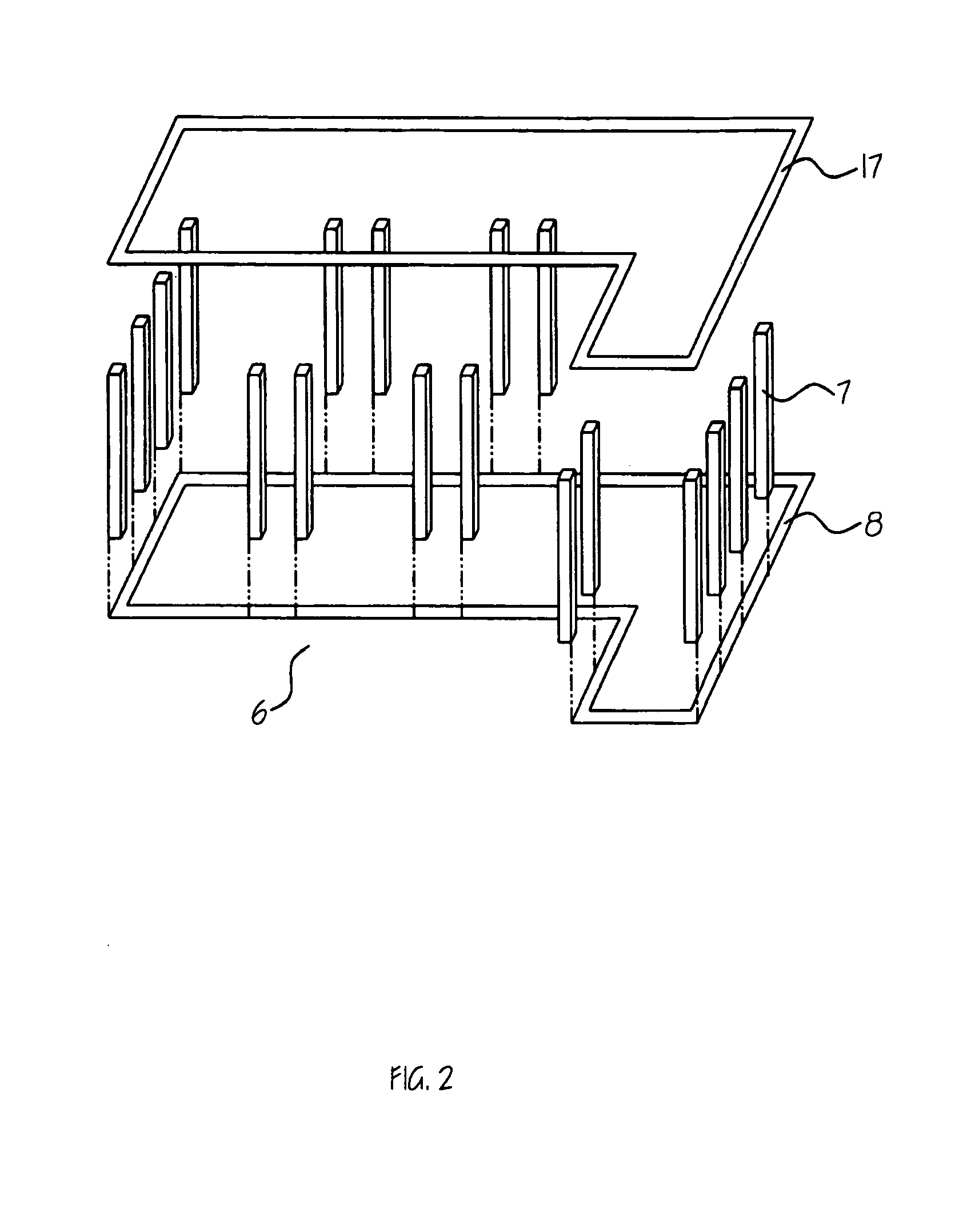
[0014]FIG. 2 is an exploded view of the lower part (6) of the solar cell module panel supporting frame structure (1). The lower part (6) of the structure (1) is in cubic form. Twenty 5 cm by 5 cm square carbon steel pipes (7) of 274 cm (9 feet) long are welded vertically on an “L” shape base (8) made with the same 5 cm by 5 cm square carbon steel pipes by cutting and welding 600 cm (20 feet) long stock. The dimension of the “L” shape base (8) is seen in the FIG. 3. The longest side (9...


PUM


Abstract

Supporting frame structure for installing solar cell module plates and incidental facilities on a house roof is provided. The supporting structure has a shape of pluralities of slope structure accompanied with cleaning accesses mounted on a rectangular cube frame. Side view of the slope structure forms a rectangular triangle on a square. The angle between the sloped top surface and the horizontal base is 3 to 75 degrees depend on the latitude of the geometric location of the place where the solar cell plate modules are installed. The maintenance access is a space through which a worker easily access to the solar cell module plates to clean the surface thereof and to replace the plates.

Description

FIELD OF INVENTION[0001]Current application relates to a metal supporting frame structure to install solar cell module plates and incidental facilities on a house roof.BACKGROUND OF THE INVENTION[0002]Since the development of photovoltaic solar cell, many kinds of solar cell itself and methods of assembling the cells into a module, including the methods of assembling the solar cells for mounting on a house roof, have been introduced. Those methods teach only how to assemble each solar cell and the parts to connect them in a planar shape. According to those illustrations, lots of heavy metal parts and ceramic insulators are necessary to make whole solar cell modules for mounting them on a roof of a house. The final solar cell module for a house may too heavy for the roof of a house. The heavy weight of the module limits the number of module plates installed on a roof and the magnitude of the power that can be obtained from them. In addition, it is not easy to clean the surface of the...

Claims


Application Information

Patent Timeline
Patent Type & Authority Patents(United States)
IPC IPC(8): H01L31/048
CPCH02S20/23H02S20/00F24J2/52Y02B10/12Y10S136/291Y02E10/50H02S20/10F24S25/00Y02B10/10
Inventor OAK, EUGENE
Owner OAK EUGENE
Learn More