

Seat structure and device for determining load on seat
- Summary
- Abstract
- Description
- Claims
- Application Information
AI Technical Summary
Benefits of technology
Problems solved by technology
Method used
Image

Examples
first embodiment
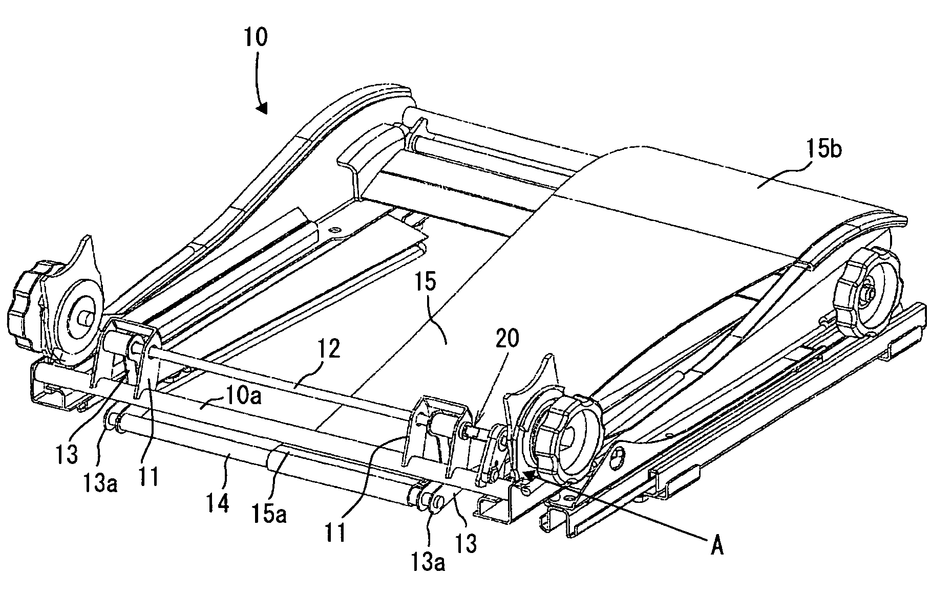
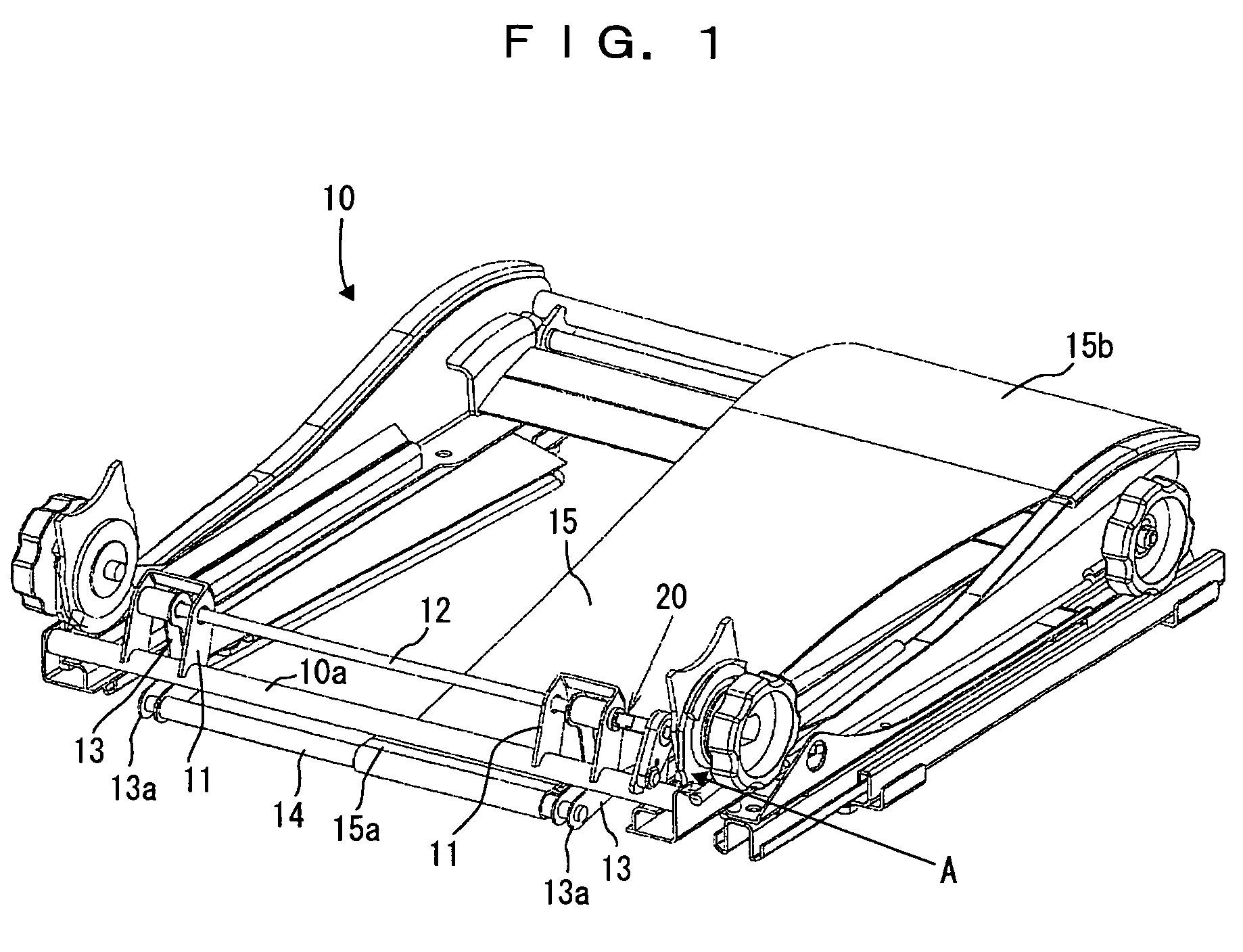
[0037]Hereinafter, the present invention will be explained in more detail based on embodiments shown in the drawings. FIG. 1 and FIG. 2 are views showing a principal portion of the present invention. As shown in these drawings, a seat cushion 10 forming the seat structure of the present embodiment includes brackets 11, a torsion bar 12, arms 13, a supporting frame 14, a cushioning member 15, a strain gauge 20, and so on.
[0038]Two brackets 11 are fixedly disposed apart from each other on a rear frame 10a arranged across the width (in the width direction) in the rear of the seat cushion 10. The torsion bar 12 is fitted to one of the brackets 11 at one end (fixed end) and supported along the width direction of the seat cushion 10. Since the torsion bar 12 is rotatably supported at its other end (movable end) by the other bracket 11, the torsion bar 12 exhibits predetermined spring characteristics due to the twisting of the movable end.
[0039]The arms 13 are provided in the vicinity of r...
third embodiment
[0051]Since the Hall IC 50 has high directivity as described above, the Hall IC 50 and the magnet 55 are required to be fixed in a manner substantially to face each other even when the arm 13 pivots. Accordingly, in the present embodiment, the bracket 51 for fixing Hall IC is fixed to protrude inwards with respect to the bracket 11 of the rear frame 10a, so as to face the arm 13. The magnet 55 is fixed on the front plate of the arm 13 which faces the rear frame 10a. As a result, as shown in FIG. 10, even when there is only one Hall IC 50 which is embedded in the bracket 51 for Hall IC, the magnet 55 is disjunctive substantially facing the Hall IC 50 within the pivoting range of the arm 13. Since the output voltage of the Hall IC 50 changes when the distance between the magnet 55 and the Hall IC 50 is varied by being taken a seat by a person on the cushioning member 15, a load on the seat by a person can be determined similarly to the third embodiment from a correlation between the o...
fifth embodiment
[0054]In the fifth embodiment shown in FIG. 12 to FIG. 14, the bracket 61 for fixing Hall IC is formed substantially in an L-shape and its bent end portion is allowed to face the arm 13 as described above. Accordingly, as shown in FIG. 15A to FIG. 15E, by making a structure of disposing a pair of magnets 66 and 67 on respective side faces of the arms 13 facing each other while sandwiching the Hall IC 60 disposed on the bent end portion, it is possible to strengthen the magnetic field working on the Hall IC 60 to enhance the sensitivity. In that event, as shown in FIG. 15A to FIG. 15E, various combinations are conceivable as a structure to arrange the magnets 66 and 67. For instance, a structure to let the same poles face each other (refer to FIGS. 15A and 15D), or to let the different poles face each other (refer to FIGS. 15B, 15C, and 15E) is conceivable. Further, it is possible to allow the different poles of respective magnets 66 and 67 adjacent to each other so that the respecti...
PUM
 Abstract
Description
Claims
Application Information