Digital torque wrench

a torque wrench and digital technology, applied in the field of hand tools, can solve the problems of thread slipping, device not being able to meet the needs of use, and not being able to achieve optimal measurement accuracy,

Active Publication Date: 2006-08-01
RYESON CORP
View PDF18 Cites 51 Cited by
  • Summary
  • Abstract
  • Description
  • Claims
  • Application Information

AI Technical Summary

Problems solved by technology

Moreover, it is not sufficient that the device simply be tightened as far as possible as this may result in stripping of the threads or vibrational problems in the resulting assembly.
However, such a device is normally not sufficiently accurate for the specifications being set forth by the automotive and aircraft industries which commonly employ such devices.
However, all currently known torque wrenches of such a design suffer from certain drawbacks resulting in less than optimally accurate measurements.
For example, if the torque wrench is used such that force is imparted along a vector other than that causing rotation of the wrench, the transducer can tend to bend which results in shearing stress on the transducer not reflective of the torque being applied.
Moreover, given the relatively uniform construction of such transducers, the shearing stress applied across the transducer is often not uniform and thus also results in inaccurate readings.
Given such localization of the mounting structure, the transducer is subjected to bending forces making measurement of only the shearing stress resulting from the torque being applied difficult.
Accordingly, conductors are provided and are typically mounted on the outside surface of the transducer, thereby lending themselves to damage through normal usage.
This can result in abrasion of the insulation provided about the conductor and ultimately the creation of an electrical short.
This is especially true in that, although not recommended, such wrenches are often used as makeshift hammers or are otherwise mishandled.
However, given the angle at which the wrench is being used, the display is not always readily perceptible as it may be rotated or positioned at a position inconvenient for the user in taking such a measurement.

Method used


Image

  • Digital torque wrench
  • Digital torque wrench
  • Digital torque wrench

Examples


Embodiment Construction

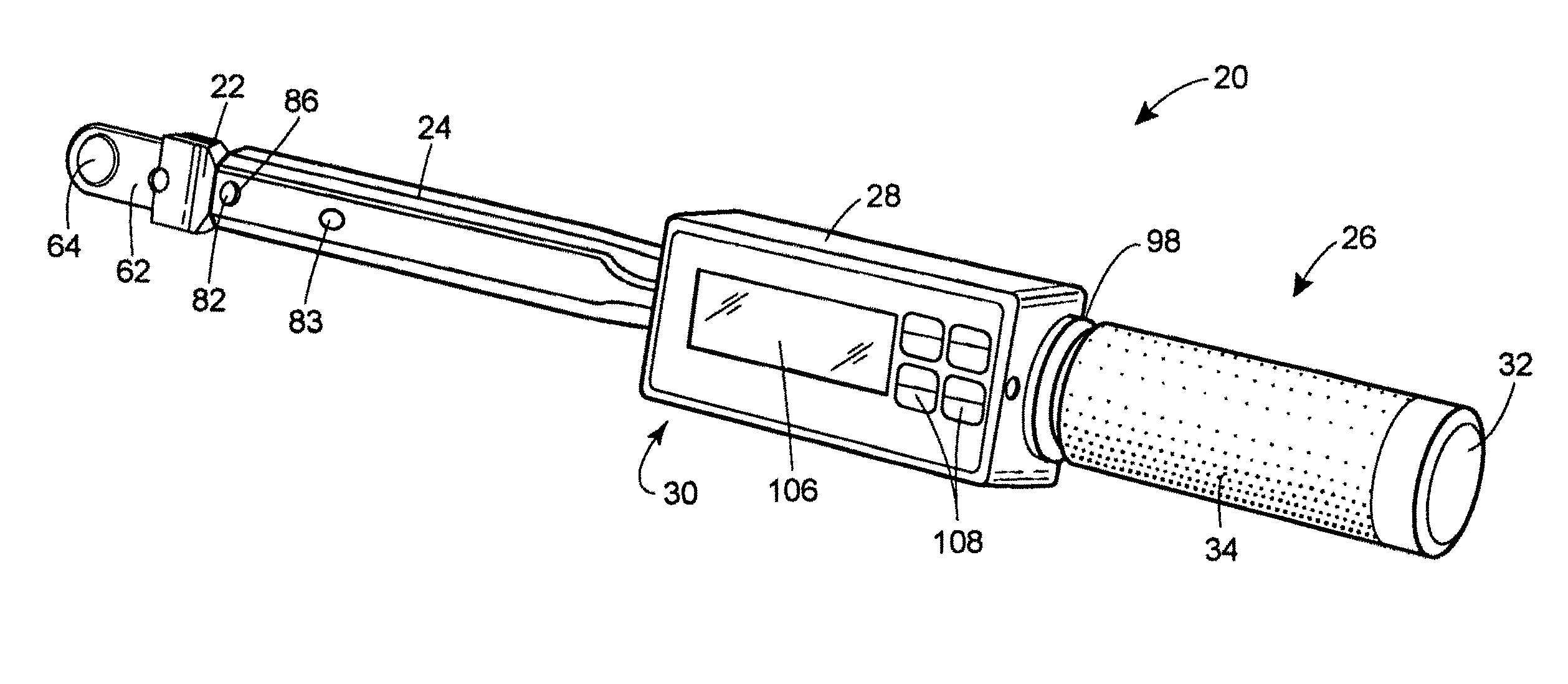
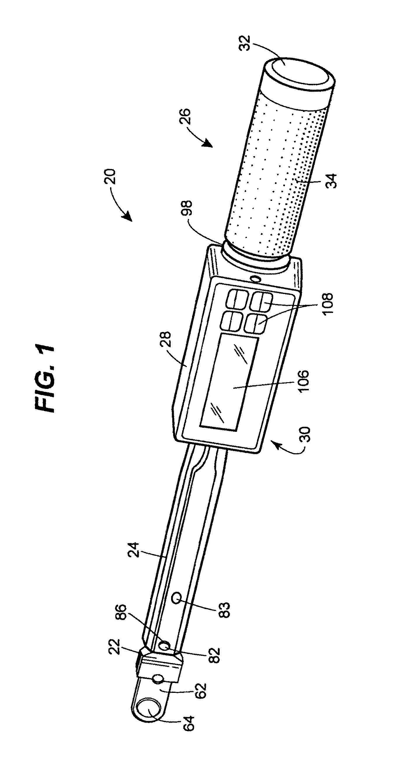
[0020]Turning now to the drawings, and with specific reference to FIG. 1, a torque wrench constructed in accordance with the teachings of the disclosure is generally referred to by reference numeral 20. As shown therein, the torque wrench 20 is of the type adapted to rotate threaded fasteners to a specified torque with a high degree of accuracy, e.g., within plus or minus one percent of the indicated torque. Such high quality, accurate wrenches are particularly applicable for use in tightly toleranced assembly processes including those of the automotive and aircraft industries. Moreover, while the torque wrench 20 is described and depicted as being a digital torque wrench, it is to be understood that its teaching could be employed for creating an analog output as well.

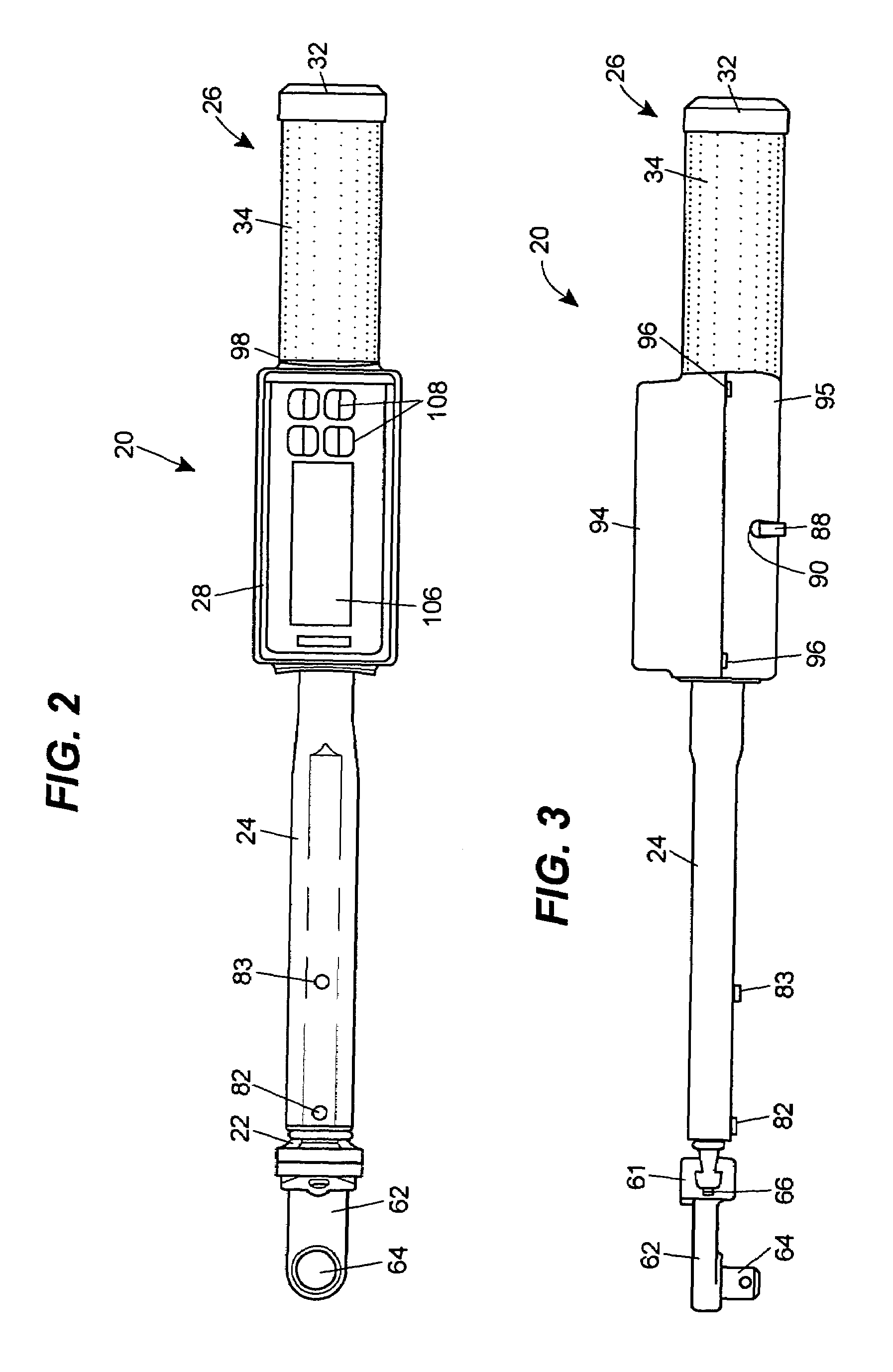
[0021]Referring now to FIGS. 1–4, the torque wrench 20 is shown to include a transducer beam 22 connected to a mounting bar 24, which in turn is connected to a handle 26. An interface module 28 is mounted to a first en...


PUM


Abstract

A digital torque wrench is disclosed having a transducer beam with a reduced thickness web therein. At least one strain gauge sensor is mounted to the internal web to measure the shearing stress within the web as the wrench is rotated. By using such a reduced thickness web, mounting the sensors in opposed orientations, mounting the transducer beam to the torque wrench handle using first and second longitudinal flanking pins, and providing the transducer beam in a tapered shape, the resulting measurement of the torque wrench is very accurate. Moreover, a rotational interface module with digital display is provided to facilitate reading of the display by the user.

Description

FIELD OF THE DISCLOSURE[0001]The disclosure generally relates to hand tools and, more particularly, relates to torque wrenches.BACKGROUND OF THE DISCLOSURE[0002]In many industrial applications, the tightening of threaded fasteners to a specific degree or torque is of extreme importance. For example, in the assembly of automobiles or aircraft, it is imperative that nuts, bolts, screws, lugs, and the like, are tightened to a pre-specified torque to ensure the resulting assembly functions properly not only at initial use, but over the long term. Moreover, it is not sufficient that the device simply be tightened as far as possible as this may result in stripping of the threads or vibrational problems in the resulting assembly.[0003]Accordingly, it has long been known to use torque wrenches for tightening such devices. Such wrenches are not only able to rotate and tighten the device, but also provide the user with some sort of indication as to exact torque being applied. Such devices can...

Claims


Application Information

Patent Timeline
Patent Type & Authority Patents(United States)
IPC IPC(8): B25B23/159B25B23/142
CPCB25B23/1425
Inventor REYNERTSON, JR., JOHN L.
Owner RYESON CORP
Why Eureka
Try Eureka