Well integrity monitoring system

a well integrity and monitoring system technology, applied in the field of well integrity monitoring system, can solve the problems of direct monitoring of strain on the well casing, serious damage or even complete loss of the bore hole, and often problematic, and can not be detected

Active Publication Date: 2005-10-25
WEATHERFORD TECH HLDG LLC
View PDF64 Cites 49 Cited by
  • Summary
  • Abstract
  • Description
  • Claims
  • Application Information

AI Technical Summary

Benefits of technology

[0008]Improved methods and apparatuses for directly monitoring well casing strain and structural integrity are disclosed that allows for monitoring of potentially damaging strain from any orientation or mode and over long stretches of well casing. In a preferred embodiment, optical fiber sensors are housed within a housing and attached to the exterior surface of the casing. The sensors may be aligned parallel, perpendicular, or at an appropriate angle to the axis of the casing to detect axial, hoop, and shear stres

Problems solved by technology

These changes, when large enough, can result in serious damage or even complete loss of the bore hole through major deformation of the well casing.
Direct monitoring of strain on a well casing, however, is often problematic because well casing strain can be caused by a number of different stresses or modes, including tensile or compressive stresses imparted along the axis of the casing, and shear stresses imparted through twisting or forces perpendicular to the casing axis.
Casing strain can occur over long stretches of casing or can be very localized, and therefore may go undetected.
The high magnitudes of strain that can cause deformation of a well casing, and/or the harsh environment down hole, can also cause apparatuses traditionally used to monitor strain to cease functioning.
Methods and apparatuses currently used to monitor well casing strain do not provide a solution to problems associated with direct strain monitoring.
Conventional str

Method used


Image

  • Well integrity monitoring system
  • Well integrity monitoring system
  • Well integrity monitoring system

Examples


Embodiment Construction

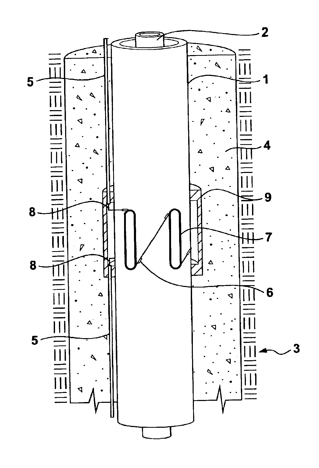
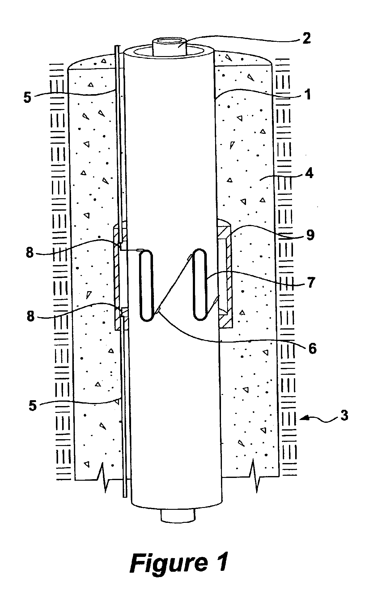
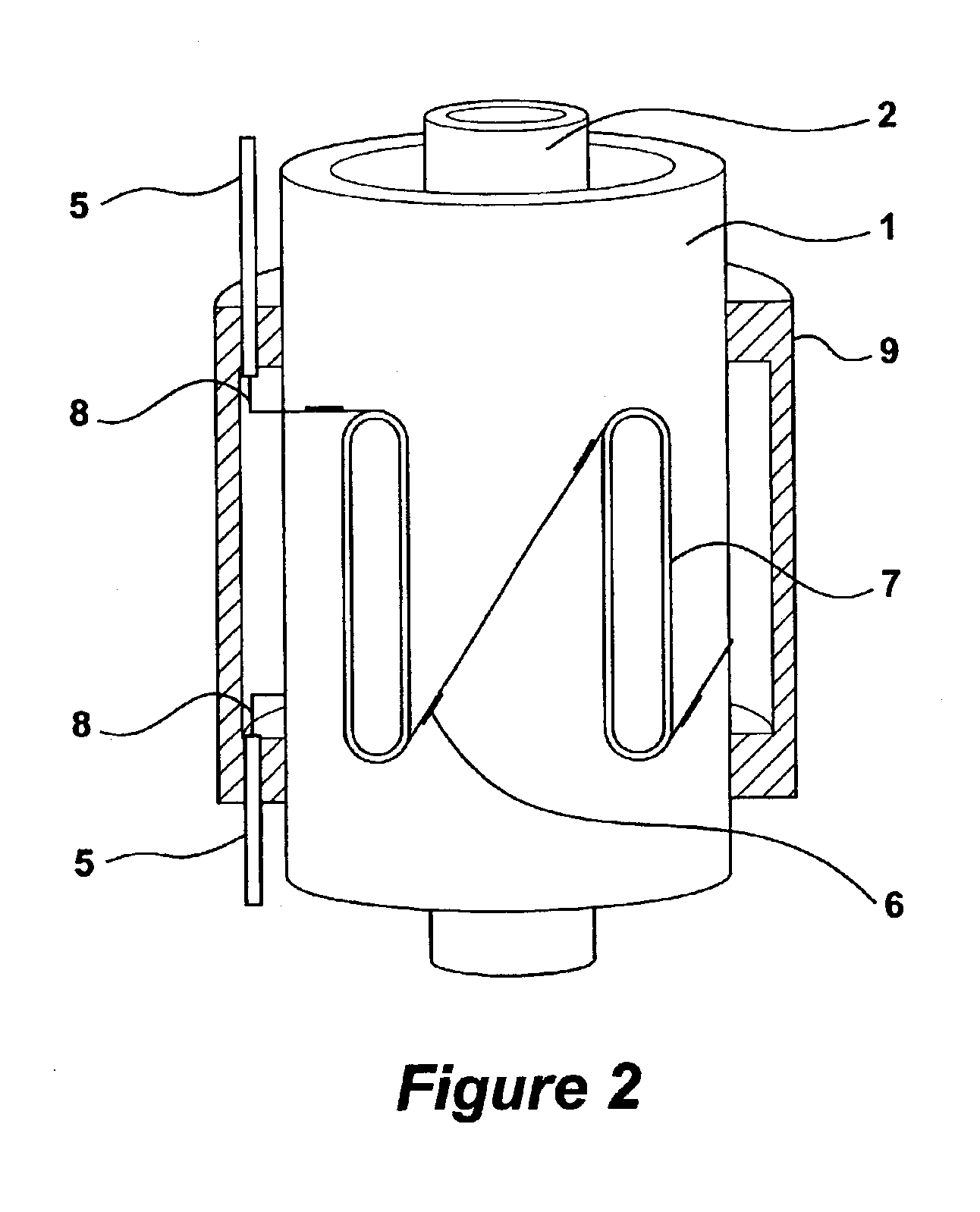
[0016]In the disclosure that follows, in the interest of clarity, not all features of an actual implementation of a well casing integrity monitoring system are described in this disclosure. It will of course be appreciated that in the development of any such actual implementation of the disclosed invention, as in any such project, numerous engineering and design decisions must be made to achieve the developers' specific goals, e.g., compliance with mechanical and business related constraints, which will vary from one implementation to another. While attention must necessarily be paid to proper engineering and design practices for the environment in question, it should be appreciated that development of a well casing integrity monitoring system would nevertheless be a routine undertaking for those of skill in the art given the details provided by this disclosure, even if such development efforts are complex and time-consuming.

[0017]The disclosed embodiments are useful in directly mon...


PUM


Abstract

Improved methods and apparatuses for directly monitoring well casing strain and structural integrity are disclosed that allows for monitoring of potentially damaging strain from any orientation or mode and over long stretches of well casing. In a preferred embodiment, optical fiber sensors are housed within a housing and attached to the exterior surface of the casing. The sensors may be aligned parallel, perpendicular, or at an appropriate angle to the axis of the casing to detect axial, hoop, and shear stresses respectively. The sensors are preferably interferometrically interrogatable and are capable of measuring both static and dynamic strains such as those emitted from microfractures in the well casing. Analysis of microfracture-induced acoustics includes techniques for assessment of relatively high frequencies indicative of the presence of microfractures. Assessment of the timing of the arrival of such acoustics at various sensors deployed along the casing further allows for the location of strain to be pinpointed.

Description

CROSS REFERENCE TO RELATED APPLICATIONS[0001]This application contains subject matter similar to that disclosed in Ser. No. 10 / 441,234, entitled “Housing On The Exterior of a Well Casing for Optical Sensors,” which is filed concurrently herewith, and which is incorporated herein by reference in its entirety.FIELD OF THE INVENTION[0002]This invention generally relates to monitoring the structural integrity and stress on a conduit, and more particularly, to monitoring the structural integrity and stress on a well casing used in oil drilling operations.BACKGROUND OF THE INVENTION[0003]Oil and gas production from petroleum reservoirs results in changes in the subsurface formation stress field. These changes, when large enough, can result in serious damage or even complete loss of the bore hole through major deformation of the well casing. Thus, it is desirable to monitor subsurface stress fields as they may indirectly indicate the stress experienced by a well casing during oil productio...

Claims


Application Information

Patent Timeline
IPC IPC(8): E21B47/00
CPCE21B47/0006E21B47/007
Inventor OGLE, PETER C.
Owner WEATHERFORD TECH HLDG LLC
Why Eureka
Try Eureka