Apparatus and method for controlling fuel injection in internal combustion engine

a technology of internal combustion engine and fuel injection, which is applied in the direction of electric control, engine starters, machines/engines, etc., can solve the problems of engine startability deterioration, and achieve the effect of favorable engine startability

Inactive Publication Date: 2006-08-01
TOYOTA JIDOSHA KK
View PDF15 Cites 113 Cited by
  • Summary
  • Abstract
  • Description
  • Claims
  • Application Information

AI Technical Summary

Benefits of technology

[0006]Accordingly, it is an objective of the present invention to provide an apparatus for controlling fuel injection in an internal combustion engine provided with an intake system injector and an in-cylinder injector, capable of ensuring favorable engine startability, and curbing a discharge of an unburned component in the engine starting state.

Problems solved by technology

For this reason, in the above-described conventional internal combustion engine, the initial combustion of the air-fuel mixture in the combustion chamber in the engine starting state, that is, an initial explosion becomes late, and there is a possibility that the engine startability becomes deteriorated.
When, however, the temperature within the combustion chamber is as low as when the engine is started, the fuel directly injected within the combustion chamber easily adheres to the inner wall of the combustion chamber and the piston, and there is a possibility that this adhered fuel is discharged as an unburned component.

Method used


Image

  • Apparatus and method for controlling fuel injection in internal combustion engine
  • Apparatus and method for controlling fuel injection in internal combustion engine
  • Apparatus and method for controlling fuel injection in internal combustion engine

Examples


first embodiment

[0020]A fuel injection controlling apparatus for an internal injection engine 11 according to the present invention will now be described with reference to FIGS. 1 to 5.

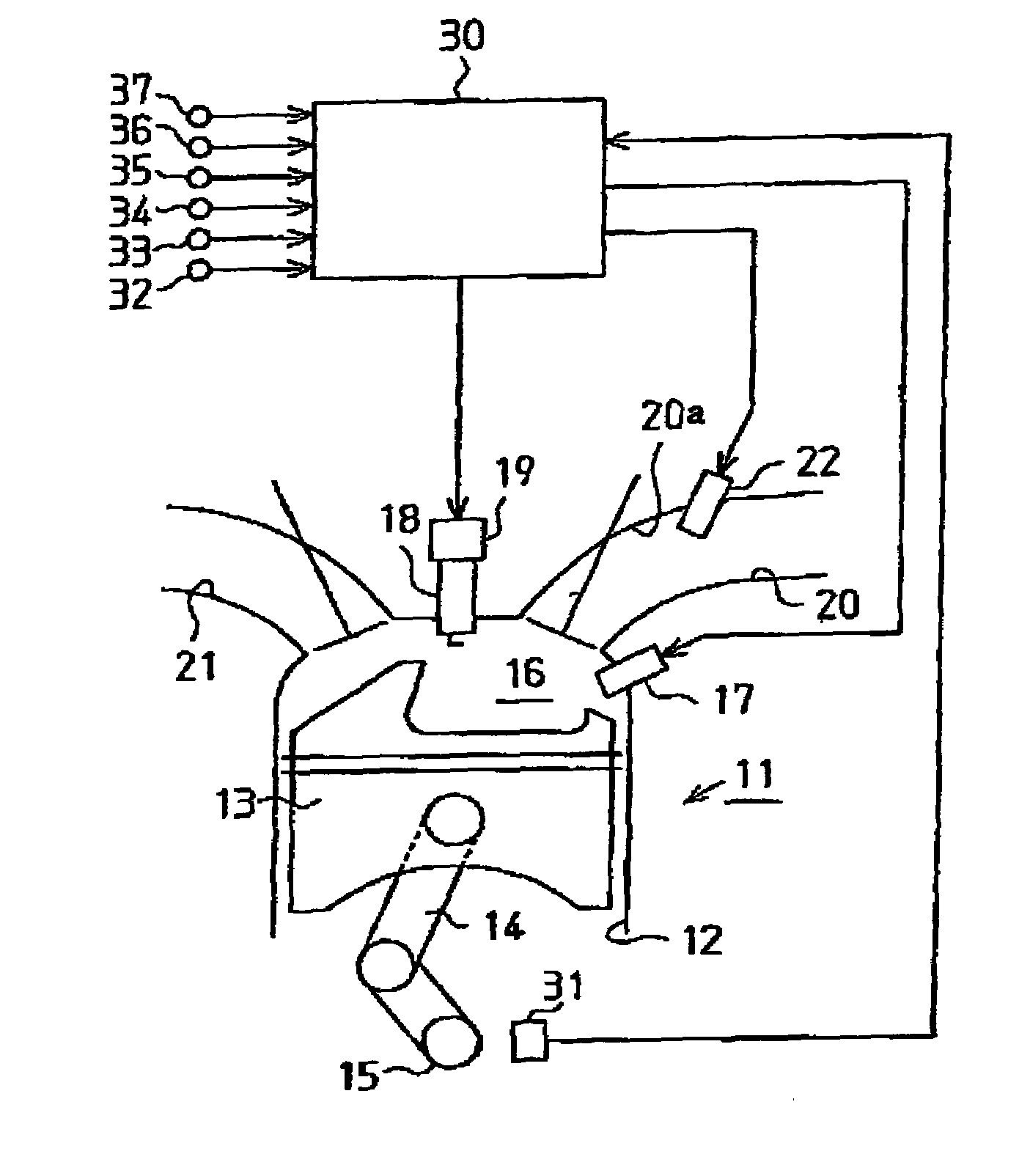
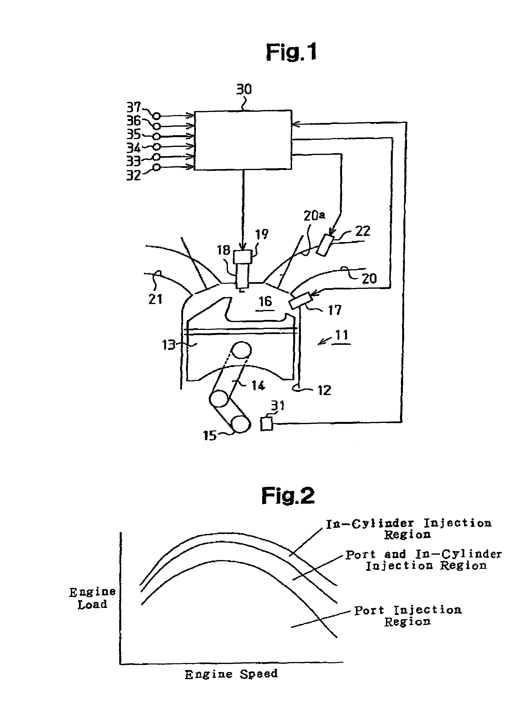
[0021]FIG. 1 illustrates the configuration of the internal combustion engine 11 to which the fuel injection controlling apparatus according to this embodiment is applied.

[0022]As shown in FIG. 1, this apparatus is configured with a four-cylinder, four-cycle internal combustion engine 11 as a core component. The internal combustion engine 11 has four cylinders 12, which are referred to as a first cylinder #1 to a fourth cylinder #4. In each of these cylinders 12 (only one of which is shown in FIG. 1), a piston 13 is provided. Each piston 13 is coupled to a crankshaft 15, which is an output shaft of the internal combustion engine 11, via a connecting rod 14 such that reciprocation of the piston 13 is converted into rotation of the crankshaft 15 through the connecting rod 14.

[0023]A combustion chamber 16 is defined in e...

second embodiment

[0077]In the second embodiment, the timing at which the fuel injected from the intake system injectors 22 reaches the combustion chambers 16 is computed on the basis of the engine speed NE, the intake passage pressure Pin, the intake air temperature THA, the coolant temperature THW, and the fuel pressure P. As the intake air flow rate Qa increases, the flow velocity thereof becomes faster, and the timing becomes earlier timing than the timing at which the fuel injected from the intake system injectors 22 reaches the combustion chambers 16. The intake air flow rate Qa may be added to each of those parameters. Also, the timing may be computed through the use of at least any of those parameters. On the other hand, with the time when a first fuel injection from the intake system injectors 22 is executed as a starting point, the timing may be measured on the basis of an elapsed time from the starting point.

[0078]The present invention may be applied to an internal combustion engine in whi...


PUM


Abstract

An internal combustion engine includes an in-cylinder injector for injecting fuel into a combustion chamber of the engine and an intake system injector for injecting fuel into an intake system connected to the combustion chamber. In a starting state of the engine, an electronic control unit (ECU) causes the in-cylinder injector to perform only the initial injection to the combustion chamber, and causes the intake system injector to perform fuel injections after the initial injection. As a result, favorable engine startability is ensured, and the emission of unburned components is suppressed in the engine starting state.

Description

BACKGROUND OF THE INVENTION[0001]The present invention relates to an apparatus and method for controlling fuel injection in an internal combustion engine that has an in-cylinder injector for injecting fuel into a combustion chamber and an intake system injector for injecting fuel into an intake system.[0002]There is known an internal combustion engine provided with an in-cylinder injector for directly injecting fuel into a combustion chamber of an internal combustion engine and an intake system injector for injecting fuel into an intake system such as an intake port or a surge tank (Japanese Laid-Open Patent Publication No. 2001-73854).[0003]In the internal combustion engine described in this Japanese Laid-Open Patent Publication No. 2001-73854, under the control of fuel injection in the engine starting state, fuel is first injected from an intake system injector for a predetermined time period. Then, fuel is injected from an in-cylinder injector. By executing such control of fuel i...

Claims


Application Information

Patent Timeline
Patent Type & Authority Patents(United States)
IPC IPC(8): F02B7/00F02B7/02F02N11/08F02B17/00F02B23/10F02B75/12F02D41/04F02D41/06F02D41/34F02D45/00F02M51/00F02M69/00F02M69/04
CPCF02B7/02F02D41/062F02D41/3094F02B23/104F02B2075/125Y02T10/123F02N19/00F02B2275/16Y02T10/12
Inventor SADAKANE, SHINJIYONEZAWA, KOICHI
Owner TOYOTA JIDOSHA KK
Why Eureka
Try Eureka