Control unit for variable valve timing mechanism

a technology of variable valve timing and control unit, which is applied in position/direction control, electric energy management, special data processing applications, etc., can solve the problems of deteriorating startability, limited amount by which the valve timing can be changed when the engine stops, and affecting the reliability of the engine, so as to achieve reliable valve phase and good engine startability

Active Publication Date: 2012-08-07
TOYOTA JIDOSHA KK
View PDF17 Cites 7 Cited by
  • Summary
  • Abstract
  • Description
  • Claims
  • Application Information

AI Technical Summary

Benefits of technology

[0008]The invention makes it possible to more reliably bring a valve phase when an engine stops to a valve phase suitable for engine starting by increasing an amount by which the valve phase can be changed after issuance of an engine stop command, thereby ensuring good engine startability in a variable valve timing mechanism with which it is difficult to change the valve phase after the engine stops.

Problems solved by technology

However, with the variable valve mechanism described in JP-A-2004-300924, the period in which the valve phase can be changed when the engine stops is limited to the period from when an engine stop command is issued until when the engine actually stops.
With a variable valve timing mechanism with which it is difficult to change the valve phase after an engine stops, the amount by which the valve timing can be changed when the engine stops is limited to a relatively small amount.
Therefore, there is a possibility that the valve phase when the engine stops does not reach a predetermined valve phase suitable for engine starting, which deteriorates startability when the engine is started next time.

Method used


Image

  • Control unit for variable valve timing mechanism
  • Control unit for variable valve timing mechanism
  • Control unit for variable valve timing mechanism

Examples


Embodiment Construction

[0044]Hereafter, an embodiment of the invention will be described with reference to the accompanying drawings. In the following description, the same or corresponding elements will be denoted by the same reference numerals. The names and functions of the elements having the same reference numerals are also the same. Accordingly, the descriptions concerning the elements having the same reference numerals will be provided only once below.

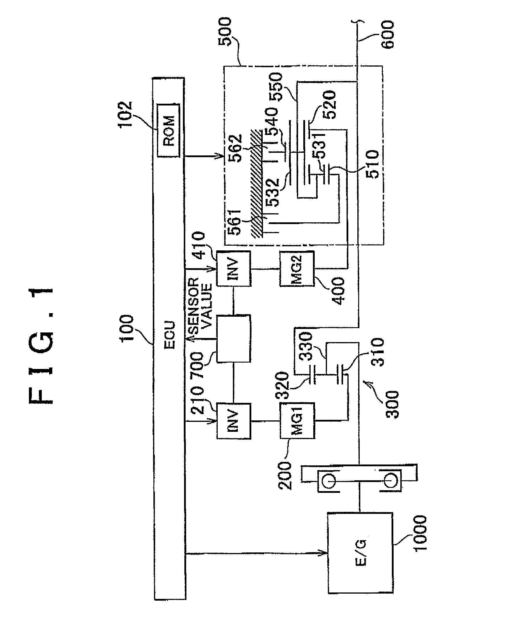
[0045]A power train of a hybrid vehicle provided with a control unit according to an embodiment of the invention will be described with reference to FIG. 1. The control unit according to the embodiment of the invention is implemented when an ECU (Electronic Control Unit) 100 executes a program stored in a ROM (Read Only Memory) 102 of the ECU 100. The ECU 100 may be divided into multiple ECUs. The program that is executed by the ECU 100 may be recorded in a CD (Compact Disc) or a DVD (Digital Versatile Disc), and distributed to the market.

[0046]As sho...


PUM


Abstract

A stop-time target phase setting unit sets a target phase CAr for an intake valve to a target phase, which is used when an engine is stopped, in response to issuance of an engine stop command. An engine stop control unit generates a series of control commands for an engine stop process in response to issuance of the engine stop command. A motoring command unit generates a first MG control command for rotating the engine using a motor for a predetermined period Tm that is counted by a timer in response to issuance of the engine stop command. Thus, the engine idles even after fuel combustion stops. In this way, the period in which the valve phase can be changed by a VVT mechanism is increased. As a result, a valve phase when the engine stops is reliably brought to the target phase that is suitable for next engine starting.

Description

BACKGROUND OF THE INVENTION[0001]1. Field of the Invention[0002]The invention relates generally to a control unit and control method for a variable valve timing mechanism, and, more specifically to a variable valve timing control that is executed when an internal combustion engine is stopped.[0003]2. Description of the Related Art[0004]A variable valve timing (VVT) mechanism that changes the phase (i.e., crank angle), at which an intake valve or an exhaust valve is opened / closed, based on the engine operating state has been used. Such variable valve timing mechanism usually changes the phase of the intake valve or the exhaust valve by rotating a camshaft, which opens / closes the intake valve or the exhaust valve, relative to, for example, a sprocket. The camshaft is rotated hydraulically or by means of an actuator, for example, an electric motor.[0005]When an engine is stopped, a VVT mechanism usually changes the valve phase toward a target phase that is suitable for next engine star...

Claims


Application Information

Patent Timeline
Patent Type & Authority Patents(United States)
IPC IPC(8): F02N11/08B60L50/15B60L50/16
CPCB60K6/365B60L11/14B60K6/445B60K6/547B60W10/06B60W10/08F02D13/0219B60W50/06B60W20/40B60L11/1862B60L15/20B60L15/2009B60L15/2054B60L7/14B60L11/123B60K6/40B60L2240/445B60W2510/0676B60W2510/244B60W2510/246B60W2710/065F16H2037/0873Y02T10/6239Y02T10/6286Y02T10/18B60L2210/40B60L2240/12B60L2240/421B60L2240/423B60L2240/441B60L2240/443B60L2240/545B60L2240/547B60L2240/549B60L2240/80B60L2260/26B60L2270/145B60L50/61B60L50/16B60L58/13Y02T10/12Y02T10/62Y02T10/64Y02T10/70Y02T10/72Y02T10/7072B60W30/18027F02D41/02
Inventor HATTORI, MASAYOSHIABE, TSUKASA
Owner TOYOTA JIDOSHA KK
Why Eureka
Try Eureka