Range switching device

a switching device and range technology, applied in mechanical equipment, gearing control, transportation and packaging, etc., can solve the problems of difficult coaxial discharging of the drive shaft of the actuator and the manual valve without changing the design of the control valve, and the oil passages are intricately formed, so as to reduce the abrasion of the spherical portion, improve the surface hardness of the pin, and bring the spherical

Inactive Publication Date: 2011-12-29
AISIN AW CO LTD
View PDF0 Cites 4 Cited by
  • Summary
  • Abstract
  • Description
  • Claims
  • Application Information

AI Technical Summary

Benefits of technology

[0026]According to a second aspect of the invention, the projecting portion protruded in the radial direction is provided between the one end side and the spherical portion, and the projecting portion is brought into abutment with the outer surface of the valve side holder when mounting the link pin, whereby it is possible to regulate the position of the spherical portion, and bring the spherical portion into exact point contact with the inner surface of the valve side holder in the shaft center position of the manual valve.
[0027]According to a third aspect of the invention, the cylindrical first hole and the second hole formed in approximately the same form as that of the outer peripheral surface of the link pin are bored in the holder portion formed at the end portion of the manual valve in such a way as to be perpendicular to each other, and a configuration is such that, as well as the link pin being fitted into the holder portion from the second hole, the spherical portion rotates at the intersection of the first hole and second hole, and makes point contact with the inner peripheral surface of the holder portion, whereby it is possible to reliably bring the spherical portion of the link pin into point contact with the holder portion in the vicinity of the shaft center of the manual valve.
[0028]According to a fourth aspect of the invention, the link pin is subjected to a quenching treatment, thus improving the surface hardness of the pin, whereby it is possible to reduce the abrasion of the spherical portion making point contact.
[0029]According to a fifth aspect of the invention, the link pin is force-fitted into the actuator side holder, and mounted integrally in the actuator side holder, whereby it is possible to eliminate a rattling of the link pin caused by a clearance between the actuator side holder and the link pin, and it is possible to compactly form the actuator side holder.

Problems solved by technology

However, oil passages are intricately formed in the control valve, and great effort and cost is necessary to change the design thereof.
However, for example, when attempting to mount the shift-by-wire range switching device described in Patent Document 1 on the control valve on which is mounted the mechanically linked range switching device, as the actuator has the thickness of a body, it is difficult to coaxially dispose the drive shaft of the actuator and the manual valve without changing the design of the control valve.
Therefore, there has been an attempt to move and drive the manual valve by linking the drive shaft of the actuator and the manual valve, the axial positions of which are offset from one another, but simply by linking the shafts, the thrust of the actuator is obliquely transmitted to the manual valve in the linked portion, and there has been a problem in that the sliding resistance between the manual valve and valve body increases due to the manual valve being moved and driven askew.

Method used


Image

  • Range switching device
  • Range switching device
  • Range switching device

Examples


first embodiment

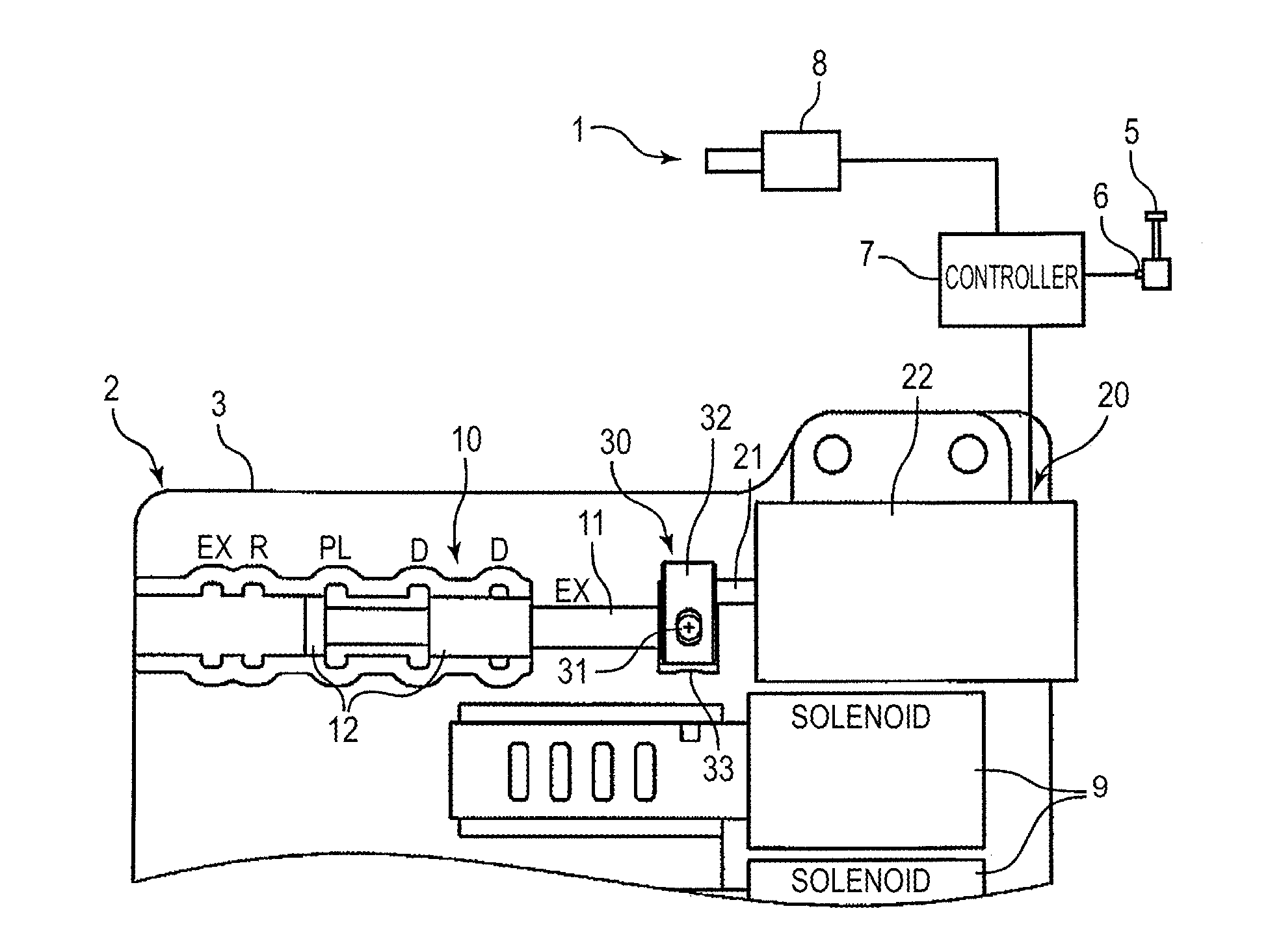
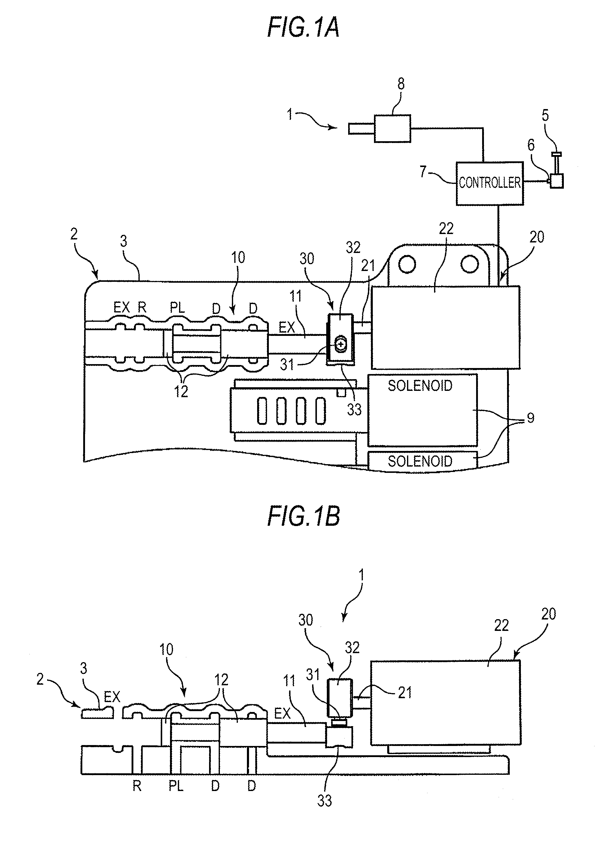
[0039]As shown in FIG. 1, a control valve 2 which hydraulically controls the engagement and disengagement of clutches and brakes which determine the transmission pathway of an automatic transmission has a vertically mounted valve body 3. As well as a plurality of linear solenoid valves 9 for adjusting the engagement pressures of the clutches and brakes being fitted in the valve body 3 in such a way as to be approximately parallel to the width direction of the valve body 3, a manual valve 10 for setting a shift range is disposed in an end portion of the valve body 3 and on the upper side of the linear solenoid valves 9.

[0040]The manual valve 10, being configured of a shaft portion 11 and a spool 12 fitted into the valve body 3, switches the axial position of the manual valve 10 in accordance with a shift range selected by a shift lever (a shift operation portion) 5 provided in the vicinity of a driver's seat, thereby setting an output condition or non-output condition (drain) of a li...

second embodiment

[0055]Next, a description will be given, based on FIGS. 4 to 7, of a second embodiment of the invention. The second embodiment differs from the first embodiment only in the configuration of the link mechanism and, as well as components identical to those of the first embodiment being given the same reference numerals and characters, a description thereof is omitted.

[0056]As shown in FIGS. 4 to 6, a link mechanism 40 which links the drive shaft 21 of the stepping motor 20 and the manual valve 10 is configured having the motor side holder 32, a link pin 41, and a valve side holder 43. The link pin 41 is such that a power transmission portion 41a is formed on the other end side which is fitted into the valve side holder 43, and the power transmission portion 41a has a pair of spherical portions 41a1 formed opposed to each other and a pair of planar portions 41a2 which, as well as being formed opposed to each other in the same way, are chamfered into a planar form.

[0057]Meanwhile, a cyl...


PUM


Abstract

A range switching device controls an actuator in response to a shift command from a shift operation portion. The actuator moves a manual valve which sets a shift range of an automatic transmission based on an axial position, and has a drive shaft which, being disposed parallel to the manual valve, is driven so as to be extendable and contractible in an axial direction. The device further includes a holder portion provided at an end portion of the manual valve, and a link pin in which one end is linked to the actuator's drive shaft, and in which the other end is a spherical portion fitted into the holder portion, and engaged in point contact with two axial sides of an inner surface of the holder portion.

Description

INCORPORATION BY REFERENCE[0001]The disclosure of Japanese Patent Application No. 2010-143743 filed on Jun. 24, 2010, including the specification, drawings and abstract thereof, is incorporated herein by reference in its entirety.BACKGROUND OF THE INVENTION[0002]1. Field of the Invention[0003]The present invention relates to a range switching device which switches the shift range of an automatic transmission such as a multispeed automatic transmission, a CVT, or a hybrid drive device, and particularly, relates to a shift-by-wire range switching device which moves a manual valve with an actuator which is controlled in response to a shift operation.[0004]2. Description of the Related Art[0005]In general, an automatic transmission has a control valve which determines a power transmission pathway by a hydraulic control, and the control valve, by moving and driving the axial position of a manual valve in accordance with a shift range selected by a shift lever, sets the output or non-outp...

Claims


Application Information

Patent Timeline
Patent Type & Authority Applications(United States)
IPC IPC(8): F16H59/12
CPCF16H61/0286F16H61/32Y10T74/2014F16H2061/326F16H2061/2861
Inventor YONEZU, TAKAYOSHISUZUKI, KEIJIODA, TAKAHITO
Owner AISIN AW CO LTD
Why Eureka
Try Eureka