Driver assistance system

a technology for drivers and assistance systems, applied in braking systems, instruments, reradiation, etc., can solve problems such as increased risk of collision, increased accident potential intensity, and aborted autonomous braking

Active Publication Date: 2013-04-16
ZF CV SYST EURO BV
View PDF11 Cites 1 Cited by
  • Summary
  • Abstract
  • Description
  • Claims
  • Application Information

AI Technical Summary

Benefits of technology

[0005]An advantage of the claimed invention is that the driver assistance system can reliably bring the motor vehicle to a standstill even if; for example, the video camera can no longer detect the preceding vehicle because the motor vehicle is rolling and pitching too strongly and, as a result, redundant detection of preceding vehicle driving data fails.
[0020]In one embodiment, the electronic actuation unit is designed to carry out a method that, when at least one of the components fails so that redundant detection of the preceding vehicle driving data becomes impossible but non-redundant detection is possible, carries out the additional steps of determining whether a last-detected distance of the preceding vehicle from the motor vehicle undershoots a predefined minimum distance, and if this is the case of suppressing an abort of the autonomous braking. Premature aborting of the autonomous braking is therefore avoided.
[0021]In other words, in situations in which redundant detection is not possible and there is already a high probability of the motor vehicle already being in a state of autonomous braking because the minimum distance from the preceding vehicle has been undershot, the autonomous braking continuous to be maintained. This prevents aborting of the autonomous braking simply because driving data are absent.

Problems solved by technology

A disadvantage with conventional driver assistance systems is that the autonomous braking is aborted if the preceding vehicle detection device no longer detects a preceding vehicle.
It has become apparent that such driver assistance systems frequently terminate the autonomous braking too early, with the result that the risk of collision and the potential intensity of the accident increase.

Method used


Image

  • Driver assistance system
  • Driver assistance system

Examples


Embodiment Construction

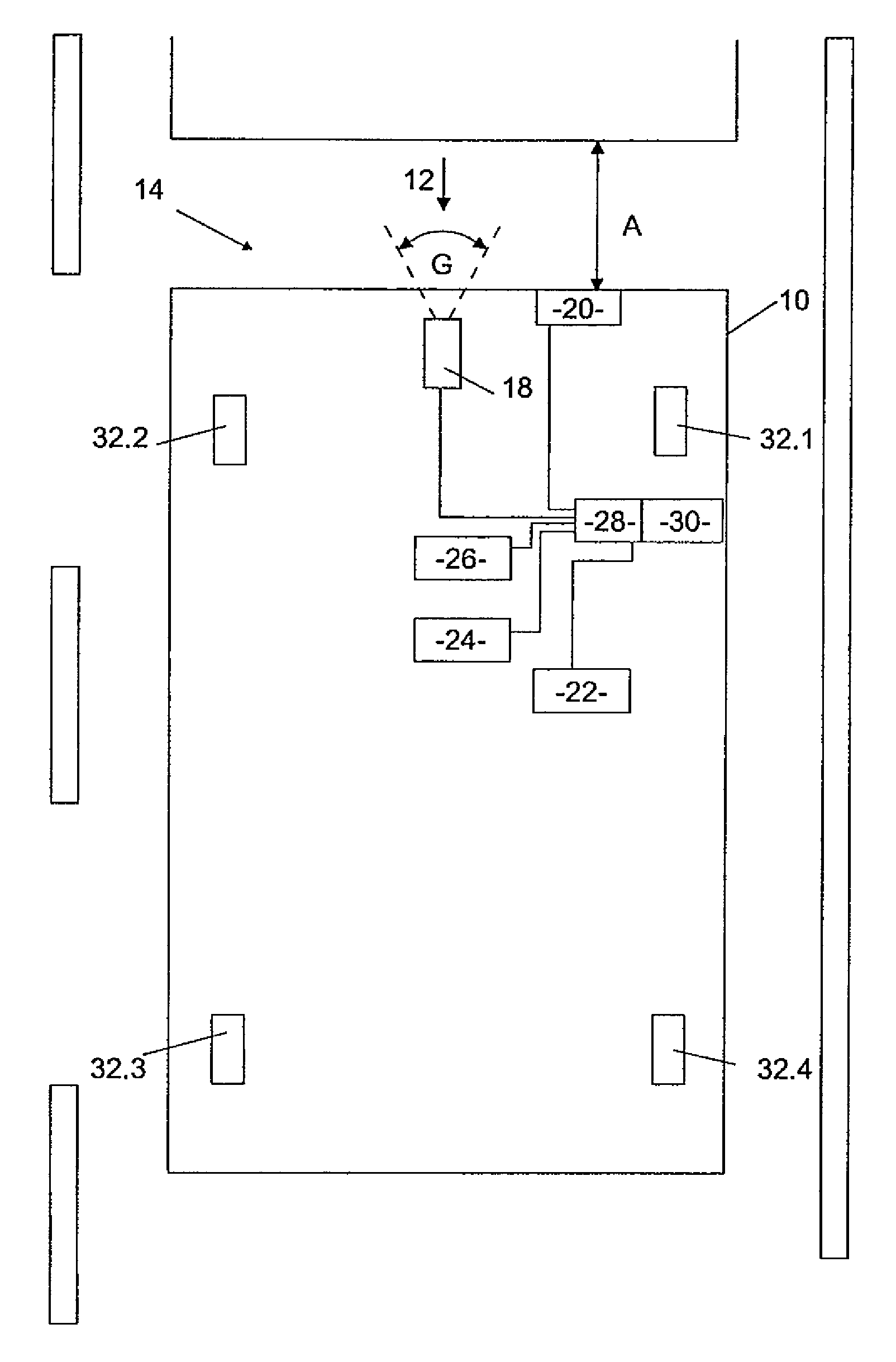
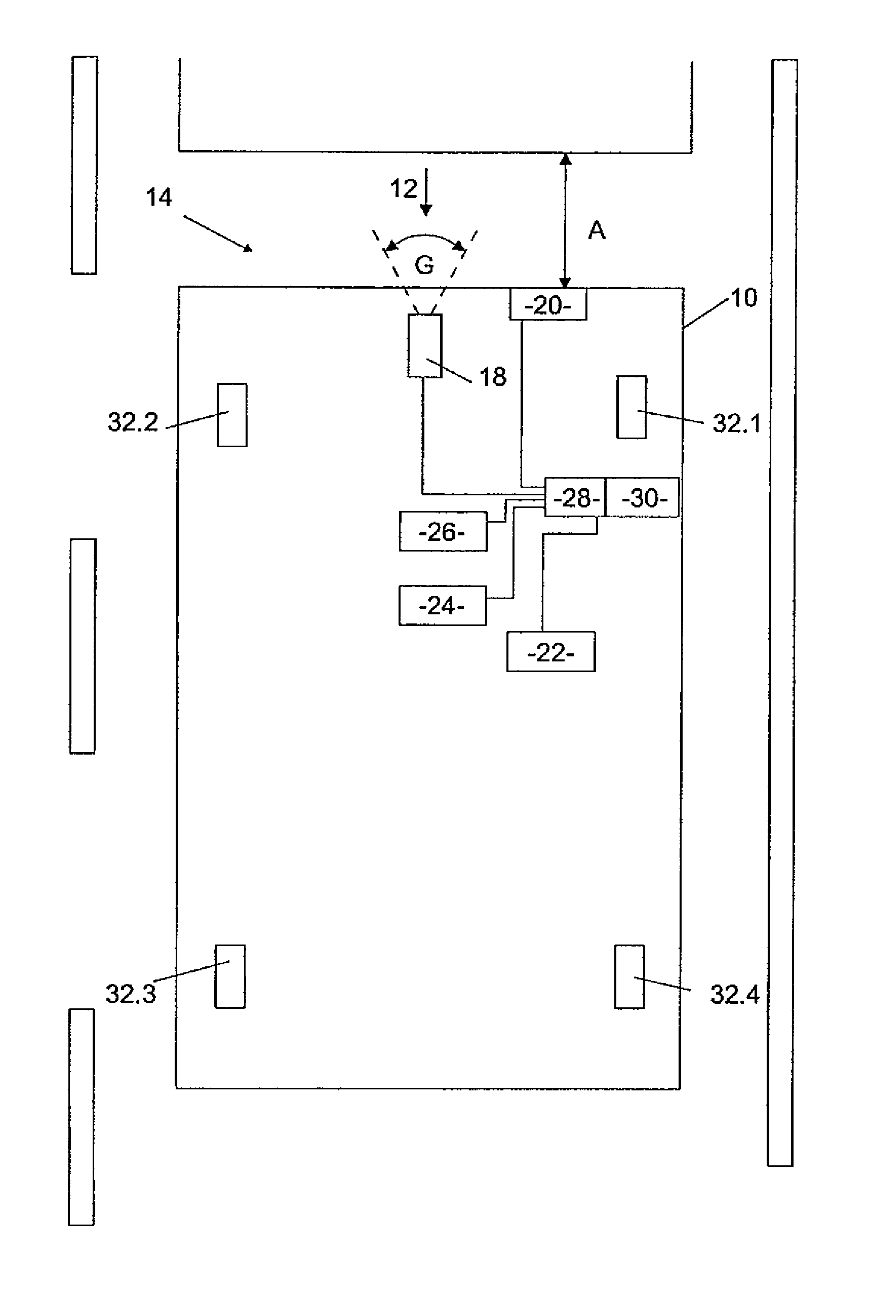
[0031]FIG. 1 shows a motor vehicle 10, which has a front side 12 on which a preceding vehicle detection device 14 is arranged. The preceding vehicle detection device 14 is designed to detect a preceding vehicle 16 and has a first component in the form of a video camera 18 with a field of vision G and a second component in the form of a distance sensor 20. The distance sensor 20 is designed to measure a distance A between the front side 12 of the motor vehicle 10 and a rear side of the preceding vehicle 16.

[0032]The motor vehicle 10 also has a speed detection device 22 in the form of a tachometer, a yaw rate sensor 24 and a deceleration sensor 26. The preceding vehicle detection device 14, the speed detection device 22, the yaw rate sensor 24 and the deceleration sensor 26 are driving data sensors that detect driving data of the motor vehicle 10. These are all connected to an electronic actuation unit 28, for example by means of cables. The electronic actuation unit 28 comprises a di...


PUM


Abstract

A driver assistance system includes a speed detector, a preceding vehicle detector having at least one video camera and at least one distance sensor for detecting the distance from a preceding vehicle, a device for determining the speed of the preceding vehicle, and an electronic control unit equipped to trigger an autonomous deceleration of the vehicle with the presence of predetermined brake trigger driving data and to terminate the autonomous deceleration with the presence of predetermined brake abortion driving data. The control unit effects: redundant detection of preceding vehicle driving data, and non-redundant detection of preceding vehicle driving data if a redundant detection is not possible. The non-redundantly detected preceding vehicle driving data is compared to preceding vehicle driving data redundantly detected within a predetermined time, and the non-redundantly detected data is used to control the autonomous deceleration if it corresponds to the redundantly detected data.

Description

FIELD OF THE INVENTION[0001]The invention generally relates to a driver assistance system for a motor vehicle, that, according to various embodiments, utilizes (a) a speed detection device for detecting driving data in the form of a speed of the motor vehicle, (b) a preceding vehicle detection device that includes at least one video camera and at least one distance sensor, (c) a preceding vehicle speed determination device for determining the speed of the preceding vehicle and (d) an electronic actuation unit configured to trigger autonomous braking of the motor vehicle when predetermined brake trigger driving data are present, and to terminate autonomous braking of the motor vehicle when predetermined brake abort driving data are present.BACKGROUND OF THE INVENTION[0002]Driver assistance systems of the general type under consideration are known and serve to reduce the severity of an accident or entirely avoid an accident through autonomous braking of a motor vehicle, which can also...

Claims


Application Information

Patent Timeline
Patent Type & Authority Patents(United States)
IPC IPC(8): G06F7/00G07C5/00
CPCB60T7/22B60T17/221G01S13/867B60T2201/022B60T2201/024G01S13/86G01S2013/9375G01S2013/9353G01S2013/9325G01S2013/9346G01S13/931G01S2013/93185G01S2013/932G01S2013/93271
Inventor BREUER, KARSTENHOFFMANN, GUIDO
Owner ZF CV SYST EURO BV
Why Eureka
Try Eureka