Vehicle engine start control device

a technology of start control device and vehicle engine, which is applied in the direction of electrical control, hybrid vehicles, instruments, etc., can solve the problems of inability to rapidly raise the engine rotation speed, passengers may feel discomfort, and the engine starting shock can be reduced, and the engine startability is favorable, and the effect of rapid and sure starting

Active Publication Date: 2015-09-22
TOYOTA JIDOSHA KK
View PDF33 Cites 8 Cited by
  • Summary
  • Abstract
  • Description
  • Claims
  • Application Information

AI Technical Summary

Benefits of technology

[0009]Consequently, since the crankshaft of the engine is hardly rotated by an external force while the engine is in the automatic stop period, the crank angle can be retained during stop of the engine with no or little change. Since the crank angle at the time of automatic stop of the engine is controlled to fall within the crank angle stop range, if the crank angle stop range is set to a crank angle range suitable for engine restart, the engine can be stopped at the crank angle suitable for engine restart in such a manner that the engine starting shock can be reduced. Therefore, since the crankshaft is stopped within or in the vicinity of the crank angle stop range at the time of restart of the engine, when the automatically stopped engine is restarted, favorable engine startability is ensured and the engine can quickly and certainly be started while suppressing a feeling of discomfort brought to a driver.
[0010]Preferably, in the engine rotation resistance control, the rotation resistance of the engine generated due to an air compression in a combustion chamber of the engine, i.e., the rotation resistance of the engine generated due to a compression of the engine is made larger during an automatic stop period of the engine as compared to the time of engine start.
[0011]Preferably, (a) the engine includes at least one of an intake valve opening / closing timing changing device advancing or delaying both opening timing and closing timing of an intake valve and an exhaust valve opening / closing timing changing device advancing or delaying both opening timing and closing timing of an exhaust valve, and wherein (b) in the engine rotation resistance control, the rotation resistance of the engine is made larger by at least one of shifting the opening timing and the closing timing of the intake valve in advance direction as compared to the time of the engine start and shifting the opening timing and the closing timing of the exhaust valve in delay direction as compared to the time of the engine start. Consequently, because an actual vehicle engine often includes the intake valve opening / closing timing changing device and the exhaust valve opening / closing timing changing device, the engine including the intake valve opening / closing timing changing device and the exhaust valve opening / closing timing changing device as described above can easily provide the engine rotation resistance control by utilizing at least one of the intake valve opening / closing timing changing device and the exhaust valve opening / closing timing changing device without particularly adding a new device.
[0012]Preferably, (a) the engine includes at least one of an intake valve opening / closing timing changing device changing opening timing and closing timing of an intake valve independently of each other and an exhaust valve opening / closing timing changing device changing opening timing and closing timing of an exhaust valve independently of each other, and wherein (b) in the engine rotation resistance control, the rotation resistance of the engine is made larger by at least one of shifting the opening timing of one or both of the intake valve and the exhaust valve in delay direction as compared to the time of the engine start, shifting the closing timing of one or both of the intake valve and the exhaust valve in advance direction as compared to the time of the engine start, and maintaining the intake valve and the exhaust valve in a closed state regardless of the crank angle of the engine. Consequently, a larger level of the rotation resistance of the engine can easily be acquired in the engine rotation resistance control as compared to the case of advancing or delaying the opening timing and the closing timing of the intake valve or the exhaust valve together.
[0013]Preferably, in the engine rotation resistance control, the rotation resistance of the engine is made larger by changing the opening timing or the closing timing of one or both of the intake valve and the exhaust valve such that an air quantity compressed in the combustion chamber of the engine in accordance with the rotation of the engine is increased. Consequently, if the engine includes the intake valve opening / closing timing changing device and the exhaust valve opening / closing timing changing device, the engine rotation resistance control can be provided and the rotation resistance of the engine can quickly and easily be increased and decreased.
[0014]Preferably, in the engine rotation resistance control, the rotation resistance of the engine is made larger by further closing an electric throttle valve adjusting an intake air amount into the engine as compared to the time of the engine start. Consequently, because an actual vehicle engine often includes the electric throttle valve, even if, for example, the engine does not include the intake valve opening / closing timing changing device and the exhaust valve opening / closing timing changing device, the engine rotation resistance control can be provided. In the engine rotation resistance control, the rotation resistance of the engine may be made larger as compared to the time of engine start by placing the electric throttle valve in a fully closed state.

Problems solved by technology

Although the engine start control device of Patent Document 1 attempts to rapidly and certainly start an engine by properly using two engine starting methods depending on a crank angle at the time of engine start, if one of the engine starting methods is selected regardless of driver's intention at the time of engine start, passengers including the driver may feel discomfort.
On the other hand, when the crank angle is out of the crank angle stop range, if the motor generator raises an engine rotation speed to start the engine, the motor generator may be unable to rapidly raise the engine rotation speed due to insufficient output power etc., of the motor generator and the flexibility in engine start may be lowered then, the passengers may feel discomfort.

Method used


Image

  • Vehicle engine start control device
  • Vehicle engine start control device
  • Vehicle engine start control device

Examples


first embodiment

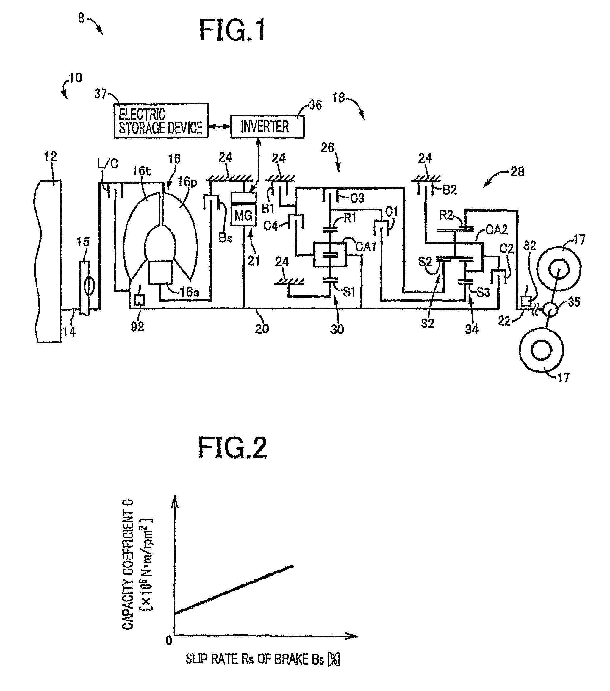
[0045]FIG. 1 is a schematic for explaining a configuration of a vehicle drive device 10 included in a vehicle 8 to which the present invention is applied. In FIG. 1, the vehicle drive device 10 is preferably employed in FR (front-engine rear-drive) type vehicles and includes an engine 12 that is an internal-combustion engine, a torque converter 16 that is a hydraulic power transmission device coupled to a crankshaft 14 of the engine 12, an automatic transmission 18 disposed between the torque converter 16 and drive wheels 17 and coupled to the torque converter 16, and an electric motor 21 for running disposed between the torque converter 16 and the automatic transmission 18 and coupled to an input shaft 20 (transmission input shaft 20) of the automatic transmission 18. In the vehicle drive device 10 configured as described above, the power of the engine 12 is transmitted from the crankshaft 14 of the engine 12 sequentially through the torque converter 16, the automatic transmission ...

second embodiment

[0123]FIG. 16 is a schematic for explaining a configuration of a vehicle drive device 308 included in a vehicle 306 of a second embodiment that is another embodiment of the present invention. The vehicle drive device 308 includes the engine 12 and a vehicle power transmission device 310 (hereinafter referred to as the “power transmission device 310”) interposed between the engine 12 and the drive wheels 17, and is preferably used for hybrid vehicles. In FIG. 16, the power transmission device 310 includes, in series, an input shaft 314 disposed on a common axial center in a transmission case 312 (hereinafter, referred to as the “case 312”) that is a non-rotating member attached to a vehicle body; a differential portion 311 as a continuously variable transmission portion coupled to the input shaft 314; an automatic transmission portion 320 as a power transmitting portion serially coupled via a transmitting member 318 on a power transmission path between the differential portion 311 an...

third embodiment

[0167]This embodiment is basically the same as the first embodiment and, therefore, differences from the first embodiment will hereinafter be described.

[0168]Although the intake valve drive device 64 is mainly made up of the cam mechanism in the first embodiment, an intake valve drive device 464 of this embodiment is not mainly made up of the cam mechanism and includes an electromagnetic valve drive mechanism capable of applying an electromagnetic force to the intake valve 62 along the direction of the reciprocating movement of the intake valve 62. Therefore, the intake valve drive device 464 has a function as an intake valve opening / closing timing changing device changing the opening timing and the closing timing of the intake valve 62 independently of each other. The operating principle of an exhaust valve drive device 468 of this embodiment is the same as the intake valve drive device 464. Therefore, the exhaust valve drive device 468 has a function as an exhaust valve opening / cl...


PUM


Abstract

A vehicle engine start control device controls a crank angle such that the crank angle falls within a predetermined crank angle stop range when an engine is automatically stopped, the vehicle engine start control device starting the automatically stopped engine if a predetermined engine start condition is satisfied, the vehicle including an automatic transmission making up a portion of a power transmission path between the engine and drive wheels, and the vehicle engine start control device providing engine rotation resistance control such that rotation resistance of the engine generated due to a change in air pressure in a combustion chamber of the engine is made larger during an automatic stop period of the engine that the engine is automatically stopped and during a change in gear ratio in a shift of the automatic transmission as compared to the time of engine start.

Description

TECHNICAL FIELD[0001]The present invention relates to a technique of controlling a vehicle engine that may automatically be stopped.BACKGROUND ART[0002]In a vehicle drive device including an engine as a drive force source for running, a vehicle engine start control device is well known that starts the automatically stopped engine if a predetermined engine start condition is satisfied. For example, this corresponds to an engine start control device described in Patent Document 1. The engine start control device of Patent Document 1 controls a crank angle of an engine (engine crank angle) to be within a predefined crank angle stop range when the engine is stopped such as when idling is stopped, for example. The predefined crank angle stop range is, for example, a range of crank angle suitable for an engine restart empirically determined in advance depending on engine parameters. For example, if an engine is restarted when the crank angle of the engine is within the crank angle stop ra...

Claims


Application Information

Patent Timeline
Patent Type & Authority Patents(United States)
IPC IPC(8): F02D41/04F02N19/00F02N11/08F02D41/00B60K6/48F02D41/06B60K6/547B60W10/06B60W20/00F02D41/02
CPCF02D41/062B60K6/48B60K6/547B60W10/06F02D41/0002F02D41/042F02N11/0814F02N19/004F02N19/005B60W20/00B60W2510/0685F02D41/023F02D2041/001F02D2041/002F02N2019/008Y02T10/42Y02T10/48Y02T10/6221B60W30/19B60W2510/0604Y02T10/40Y02T10/62
Inventor KATO, SHUNYAMATSUBARA, TOORUKUMAZAKI, KENTATABATA, ATSUSHI
Owner TOYOTA JIDOSHA KK
Why Eureka
Try Eureka