Fuel injector

a fuel injector and injector technology, applied in the field of fuel injectors, can solve the problems of uncontrollable bouncing and the variation of the piezoactuator lift by up to 30%, and achieve the effect of simplifying the compensation of linear deformation and reducing the dependence of valve lift on fuel pressur

Inactive Publication Date: 2006-08-01
ROBERT BOSCH GMBH
View PDF11 Cites 13 Cited by
  • Summary
  • Abstract
  • Description
  • Claims
  • Application Information

AI Technical Summary

Benefits of technology

[0005]An example embodiment of a fuel injector according to the present invention may have the advantage that the dependence of the valve lift on the fuel pressure is substantially reduced by pressure-compensating measures. Compressive oscillations and actuator oscillations are decoupled. This is made possible by a sleeve in which the actuator is encapsulated, the stiffness of the sleeve and the actuating piston being selected such that a linear deformation of the sleeve is compensated by a corresponding linear deformation of the actuator and the actuating piston, which is disposed on the downstream side of the actuator.
[0006]It may be advantageous, in particular, if the actuator is prestressed in a simple manner by a spring, which is clamped between an actuating piston that is in operative connection with the actuator, and a sleeve that is joined to the housing of the fuel injector.
[0007]Furthermore, it may be advantageous if a prestressing of the actuator is accomplished via a spring sleeve, which prestresses the two end faces of the actuator against each other via a support component and a shoulder of the actuating piston.
[0008]Due to the stationary arrangement of the second sleeve on the housing of the fuel injector, oscillations caused by the fuel pressure are effectively damped.
[0009]The stiffness of the various materials of the bellows and the sleeve of the actuator are in this case selected in such a way that the linear deformations are compensated.
[0010]In an advantageous manner, the first sleeve may also be encapsulated in a tube so as to avoid transverse forces, which make the longitudinal compensation more difficult, and be sealed by a seal, so that only the end face is acted on by a force, but not the side surface of the sleeve encapsulating the actuator. This simplifies the compensation of the linear deformation.

Problems solved by technology

A particular disadvantage of the fuel injector described in German Patent Application DE 195 34 445 is that, due to the influence of the fuel pressure, the lift of the piezoactuator can vary by up to 30% of the nominal lift, the sealing surfaces notwithstanding.
Furthermore, it is disadvantageous that, due to the length of the valve needle, oscillations are induced therein, which can lead to uncontrollable bouncing.

Method used


Image

  • Fuel injector
  • Fuel injector
  • Fuel injector

Examples


Embodiment Construction

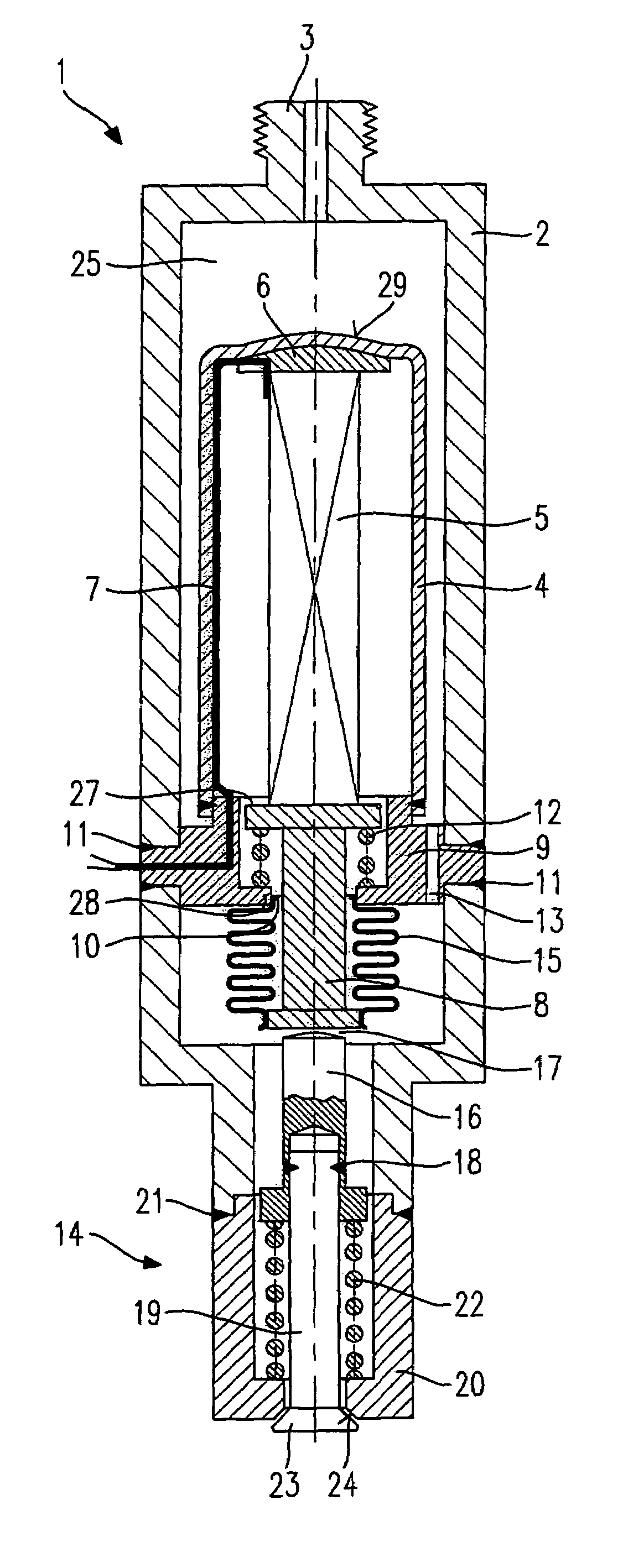
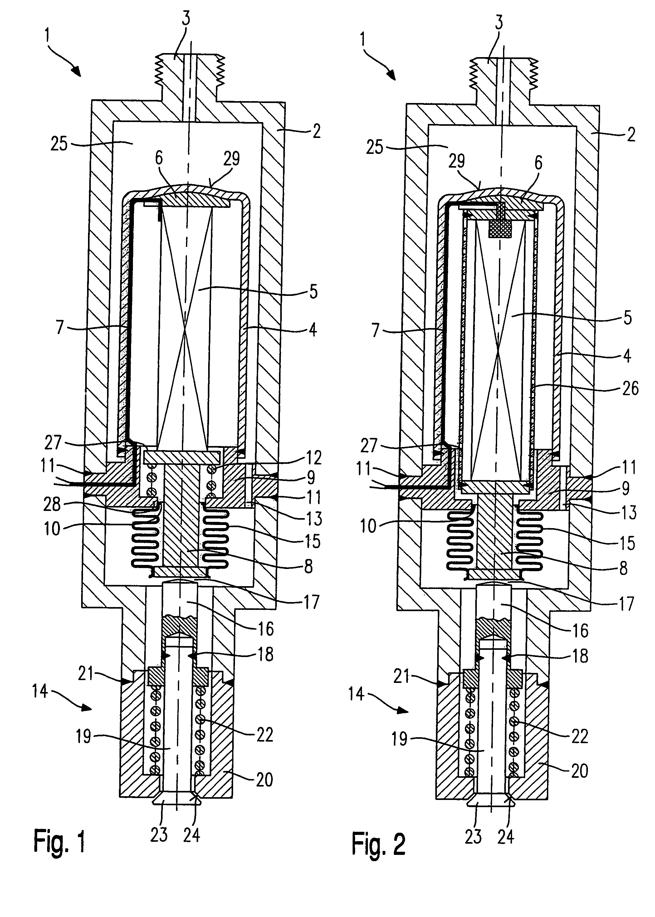
[0015]A first exemplary embodiment of a fuel injector 1 according to the present invention, shown in FIG. 1, is configured in the form of a fuel injector 1 for fuel-injection systems of mixture-compressing internal combustion engines having externally supplied ignition. Fuel injector 1 is particularly suited for the direct injection of fuel into a combustion chamber (not shown) of an internal combustion engine.

[0016]Fuel injector 1 encompasses a housing 2, which includes an hydraulic connection 3 for the supply of fuel. Arranged inside housing 2 is a first sleeve 4 in which an actuator 5 is encapsulated. In the first exemplary embodiment, actuator 5 is designed as piezoelectric actuator 5. On the inflow side, actuator 5 is braced on first sleeve 4 via a support component 6. Also guided in first sleeve 4 is an electrical line 7 for contacting actuator 5.

[0017]On the downstream side, actuator 5 is braced on an actuating piston 8, which penetrates a second sleeve 9 through an opening 1...


PUM


Abstract

A fuel injector for the direct injection of fuel into the combustion chamber of an internal combustion engine includes an actuator, which is encapsulated in a first sleeve and is sealed from an inner chamber of the fuel injector; a valve needle actuable by the actuator, which includes a valve-closure member cooperating with a valve-seat surface to form a sealing seat; and a locking spring, by which the valve needle is acted upon in such a manner that the valve-closure member is held in sealing contact at the valve-seat surface. An inflow-side end face of the first sleeve is dimensioned such that a linear deformation of the first sleeve, caused by the fuel pressure present at the inflow-side end face, is compensated by a linear deformation of the actuator and an activating piston extending the actuator.

Description

FIELD OF THE INVENTION[0001]The present invention is directed to a fuel injector.BACKGROUND INFORMATION[0002]A fuel injector is described in German Patent Application No. DE 195 34 445. The fuel injector for internal combustion engines described therein includes a nozzle needle, which is axially movable in a nozzle body and can be actuated by a piezoelectric actuator and which is held in a closing position by a compression spring. The fuel is supplied by an external source at a freely adjustable pressure. The nozzle needle has a central bore, and the actuator, which concentrically surrounds the nozzle needle, is sealed from the fuel pressure by a sealing surface.[0003]A particular disadvantage of the fuel injector described in German Patent Application DE 195 34 445 is that, due to the influence of the fuel pressure, the lift of the piezoactuator can vary by up to 30% of the nominal lift, the sealing surfaces notwithstanding.[0004]Furthermore, it is disadvantageous that, due to the ...

Claims


Application Information

Patent Timeline
Patent Type & Authority Patents(United States)
IPC IPC(8): B05B1/08B05B1/30B05B3/04F02M59/00F02B75/12F02M51/06F02M61/08F02M61/16F02M63/00
CPCF02M51/0603F02B2075/125Y02T10/123F02M61/167F02M61/08Y02T10/12
Inventor MAEURER, WALTERDOEBLER, ULRICHSTIER, HUBERTHOHL, GUENTHERDEPONTE, RENE
Owner ROBERT BOSCH GMBH
Why Eureka
Try Eureka