
Golf ball

a golf ball and multi-piece technology, applied in the field of golf balls, can solve the problems of poor poor spin receptivity and controllability of the ball on the shot taken with the iron, and hard and unpleasant feeling, and achieve good balance in rebound and excellent distance.

Active Publication Date: 2006-08-01
BRIDGESTONE SPORTS
View PDF12 Cites 10 Cited by
  • Summary
  • Abstract
  • Description
  • Claims
  • Application Information

AI Technical Summary

Benefits of technology

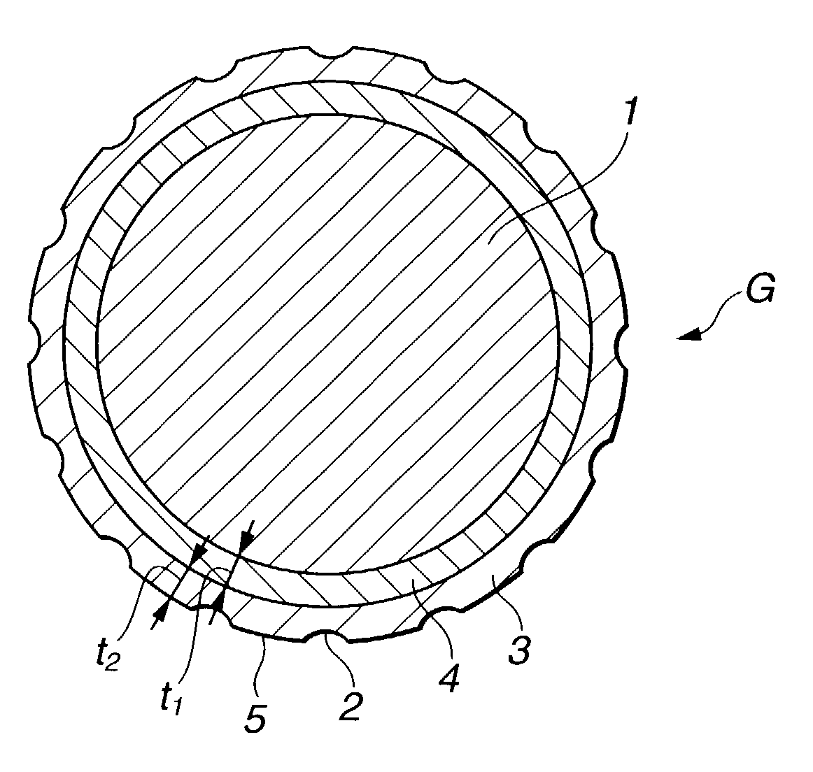
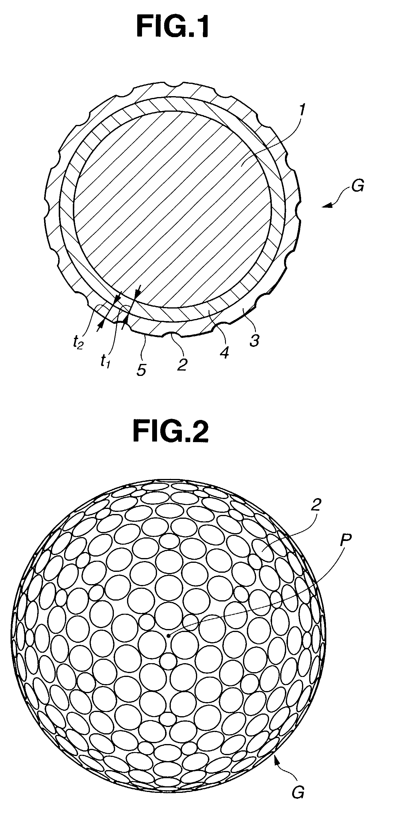
[0007]It is therefore an object of the invention to provide a multi-piece golf ball which is composed of a solid core enclosed within a plurality of thermoplastic resin layers, in which the relative hardnesses and absolute hardnesses of the constituent members have been adjusted so as to achieve a good balance in rebound, spin and feel, and which has been provided with an optimal dimple configuration to confer excellent distance.
[0008]The present invention relates to golf balls comprising an elastic solid core, a mantle layer, and a resin cover having a plurality of surface dimples. We have discovered that when the difference in Shore D hardness between the cover and the mantle layer is at most 10 and the dimples have a total volume of 280 to 350 mm3, the golf balls are endowed with excellent rebound, spin and feel, and can also achieve increased distance.
[0011]It is advantageous for the mantle layer to be composed primarily of an ionomer resin and to contain also an olefin elastomer, and for the cover to be composed primarily of a polyurethane elastomer.

Problems solved by technology

However, although such a construction provides an excellent distance, the deformation at the time of impact is smaller than that of thread-wound balls, resulting in a hard and unpleasant feel.
Also, the small deformation means that the surface area of contact with the clubface is small, giving the ball a poor spin receptivity and poor controllability on shots taken with an iron.
Yet, these improvements have been accompanied by a number of new problems, such as a decline in carry—originally a desirable attribute of solid ball constructions, due to a smaller rebound.
Another new problem has been the ball's excessive receptivity to spin when hit for distance with a wood club, particularly a driver, resulting instead in a somewhat skying shot that fails to achieve the desired distance.
Little progress has been made in overcoming these problems.

Method used


Image

  • Golf ball
  • Golf ball
  • Golf ball

Examples


examples

[0051]Examples of the invention and comparatives examples are provided below by way of illustration and not by way of limitation.

examples 1 and 4

, and Comparative Examples 3 and 4

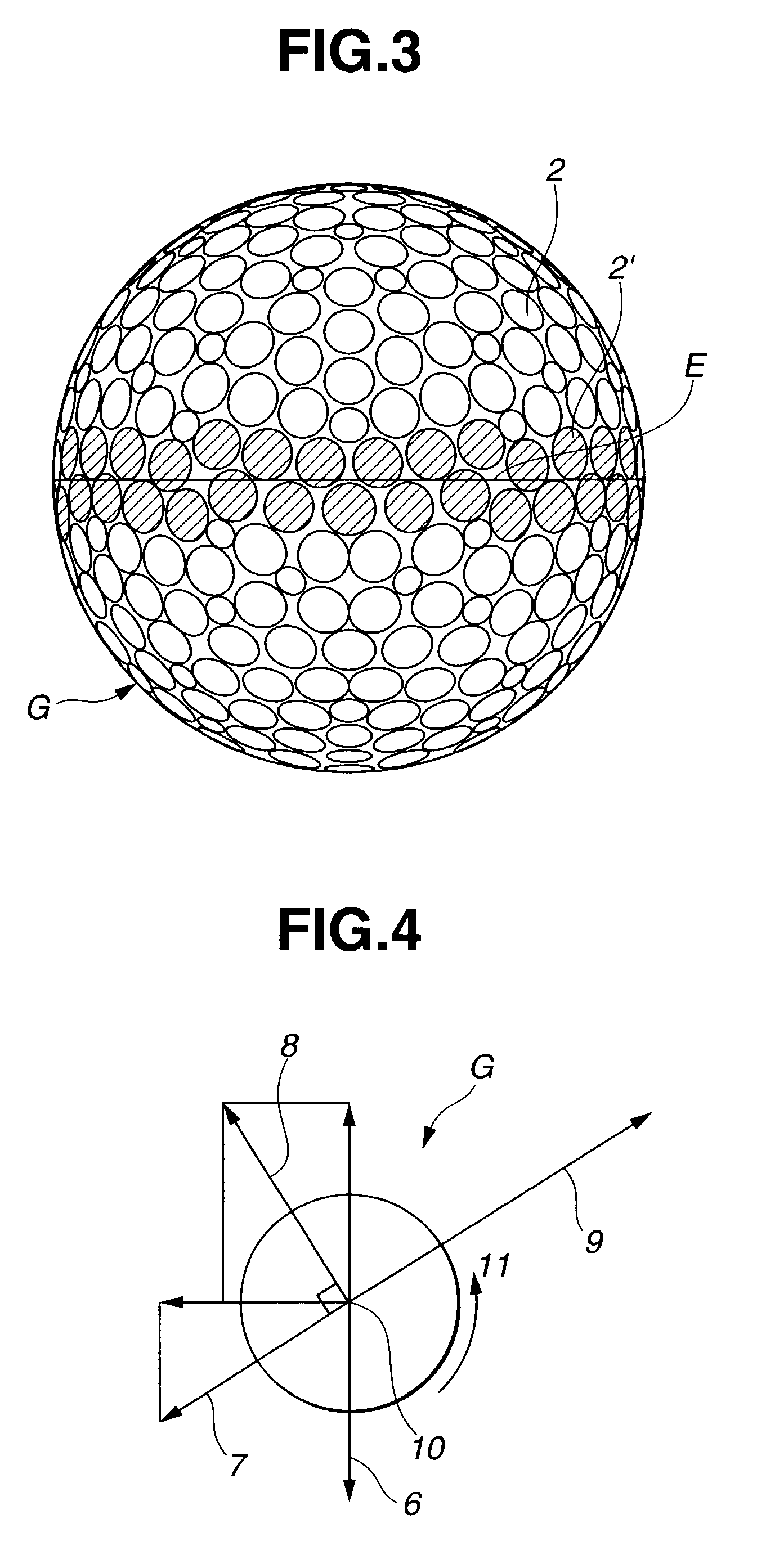
[0059]Next, the lift, drag and total distance were measured for golf balls obtained in Examples 1 and 4 according to the invention and Comparative Examples 3 and 4.

[0060]The golf ball in Example 1 had the combination shown in Table 2. The golf balls in Example 4 and Comparative Examples 3 and 4 had the respective dimple sets B, C and D (Table 1), aside from which they were made of the same materials and had the same ball construction as in Example 1.

[0061]In the tests, a driver (number one wood) mounted on a swing machine was used to hit the balls at an initial velocity of 72 m / s, a launch angle of 10° and a spin of 2,700 rpm. The results are shown in Table 3.

[0062]

TABLE 3ComparativeVelocityExampleExamplePosition ofVSpinReynolds1434ball(m / s)(rpm)number(A)(B)(C)(D)Immediately72.02,700200,000CL0.1610.1570.1660.152after impactCD0.2180.2250.2150.237CL / CD0.7360.6980.7720.641High point of41.42,400120,000CL0.2170.2130.2230.208trajectoryCD0.2480.2530.2530.2...


PUM


Abstract

In a golf ball comprising an elastic solid core, a mantle layer, and a resin cover having a plurality of dimples, the difference in Shore D hardness between the cover and the mantle layer is at most 10, and the dimples have a total volume of 280–350 mm3. This combination of features provides the golf ball with an excellent balance of rebound, spin and feel, and an outstanding total distance.

Description

BACKGROUND OF THE INVENTION[0001]1. Field of the Invention[0002]The present invention relates to a multi-piece solid golf ball of outstanding rebound, spin, feel and distance which has an elastic solid core enclosed within a plurality of resin layers of differing physical characteristics.[0003]2. Prior Art[0004]Golf balls in recent years have seen an overwhelming shift in preference take place from thread-wound constructions to solid constructions on account of the excellent distance achieved by the latter. At first, a solid construction typically referred to a two-piece solid golf ball in which the center, which represents most of the ball, is composed of a solid rubber core of excellent impact resilience and is enclosed within a hard resin cover such as one made of ionomer resin for protection from external damage.[0005]However, although such a construction provides an excellent distance, the deformation at the time of impact is smaller than that of thread-wound balls, resulting i...

Claims


Application Information

Patent Timeline
IPC IPC(8): A63B37/12A63B37/14A63B37/04A63B37/06A63B37/00
CPCA63B37/0003A63B37/0004A63B37/12A63B37/0017A63B37/0018A63B37/0019A63B37/002A63B37/0021A63B37/0031A63B37/0033A63B37/0035A63B37/0043A63B37/0065A63B37/0066A63B37/0075A63B37/0078A63B37/008A63B37/0084A63B37/0087A63B37/0089A63B37/009A63B37/0092A63B37/0096
Inventor KASAHIMA, ATSUKITAKESUE, RINYAMAEHARA, KAZUTO
Owner BRIDGESTONE SPORTS
Learn More