Fixation screw, graft ligament anchor assembly, and method for securing a graft ligament in a bone tunnel

a technology of graft ligaments and fixing screws, which is applied in the field of medical devices and methods, can solve problems such as torn or ruptured ligaments, and achieve the effect of strengthening the retention of screws in bon

Inactive Publication Date: 2006-08-01
SKLAR JOSEPH H +2
View PDF72 Cites 121 Cited by
  • Summary
  • Abstract
  • Description
  • Claims
  • Application Information

AI Technical Summary

Benefits of technology

[0011]An object of the invention is to provide a fixation screw configured for disposition in cortical bone portions, so as to strengthen the retention of the screw in the bone.

Problems solved by technology

In many cases, ligaments are torn or ruptured as a result of accidents.

Method used


Image

  • Fixation screw, graft ligament anchor assembly, and method for securing a graft ligament in a bone tunnel
  • Fixation screw, graft ligament anchor assembly, and method for securing a graft ligament in a bone tunnel
  • Fixation screw, graft ligament anchor assembly, and method for securing a graft ligament in a bone tunnel

Examples


Embodiment Construction

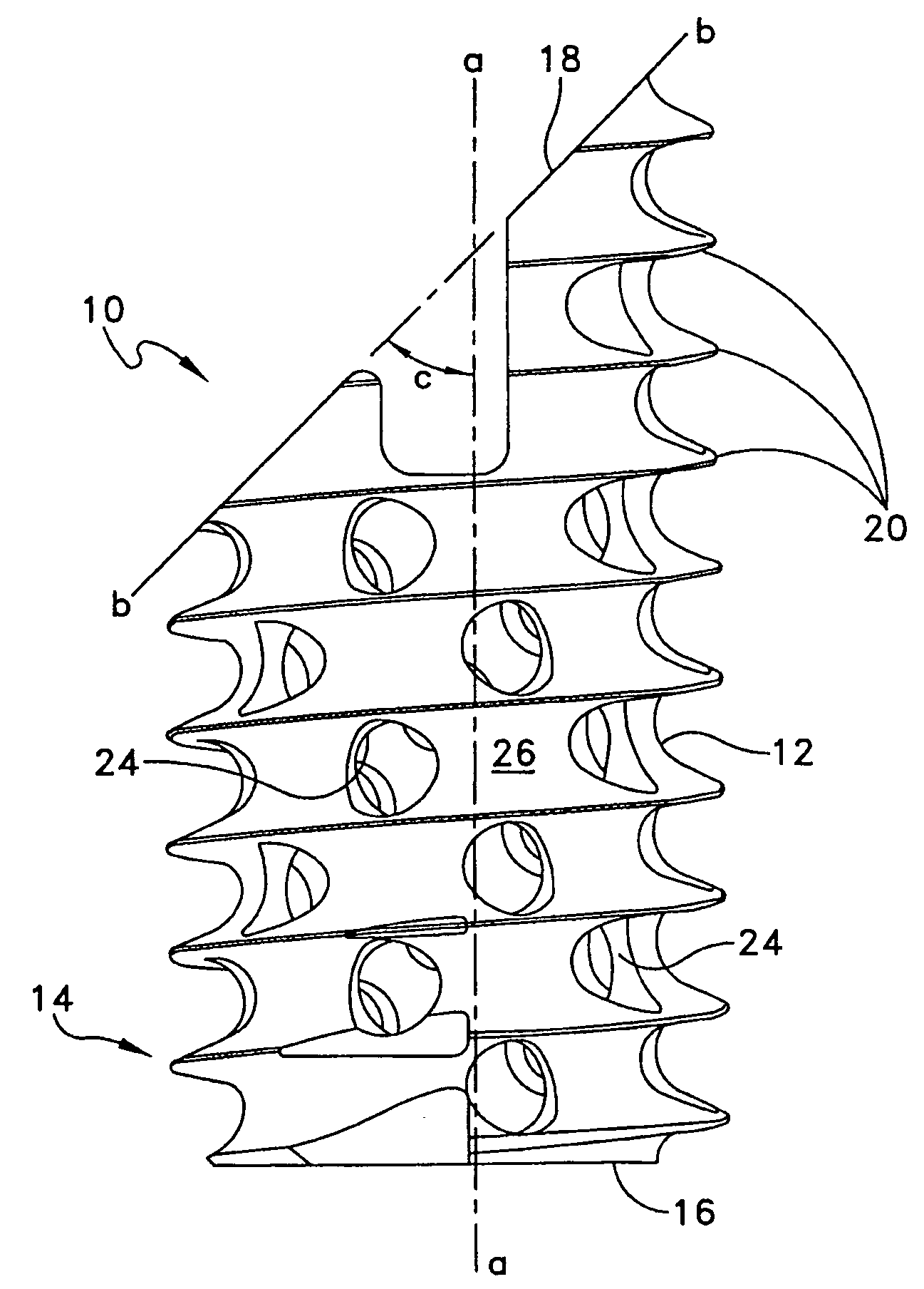
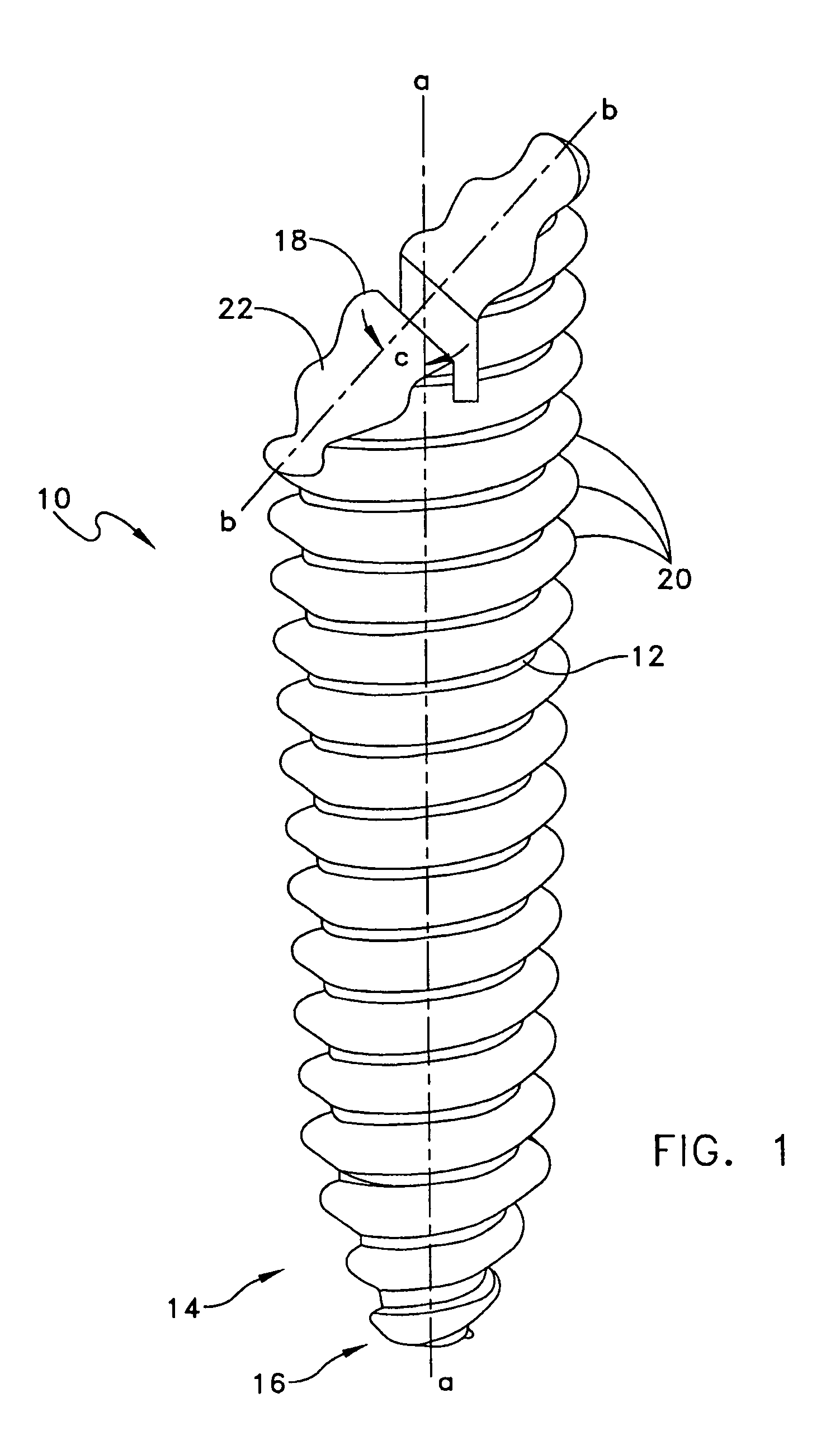
[0028]Referring to FIG. 1, it will be seen that an illustrative fixation screw 10 includes an elongated shank 12 having a distal end portion 14, which may be generally conically-shaped, as shown in FIG. 1, and have a generally pointed distal end 16. The shank 12 is further provided with a proximal end 18 defining an end plane b—b. A central axis a—a extends from the distal end 16 to the proximal end 18. The plane b—b is disposed transversely to the axis a—a and at an angle c thereto, the angle c being other than a normal angle, and preferably of about 40°–55°. The proximal end 18 may comprise a generally planar surface 22, as illustrated in FIG. 1. Screw threads 20 are disposed on the shank 12 and extend from the distal end 16 to the proximal end 18.

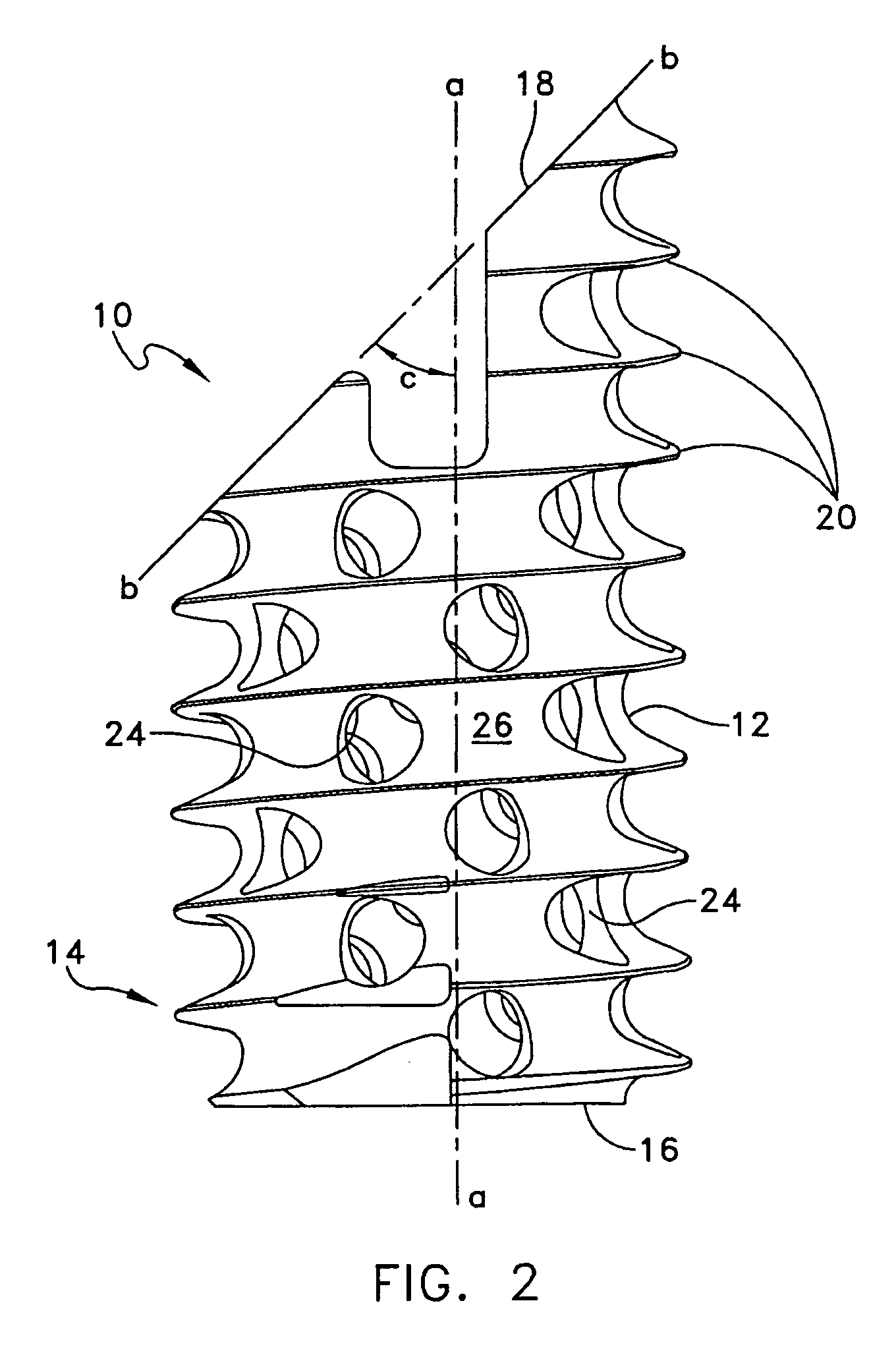
[0029]Referring to FIG. 2, it will be seen that the fixation screw 10 may be of tubular structure and provided with apertures 24 extending through sidewalls 26 thereof, facilitating in-growth of bone to further secure the screw in place ...


PUM


Abstract

A fixation screw, graft ligament anchor assembly, and method for fastening a graft ligament in a bone tunnel. The screw comprises an elongated shank having a distal end and a proximal end, and a central axis extending from the distal end to the proximal end. Screw threads are disposed on the shank and extend from the distal end to the proximal end. The proximal end defines an end plane disposed transversely to the axis and at an angle thereto other than a normal angle.

Description

REFERENCE TO RELATED APPLICATION[0001]This is a continuation-in-part of (1) pending prior U.S. patent application Ser. No. 09 / 248,523, filed Feb. 9, 1999, now U.S. Pat. No. 6,533,816 by Joseph H. Sklar for GRAFT LIGAMENT ANCHOR AND METHOD FOR ATTACHING A GRAFT LIGAMENT TO A BONE; and (2) is a continuation in part of U.S. patent application Ser. No. 09 / 304,885, filed May 4, 1999 now abandoned by Joseph H. Sklar, Harold M. Martins and Richard F. Wenstrom, Jr. for GRAFT LIGAMENT ANCHOR AND METHOD FOR ATTACHING A GRAFT LIGAMENT TO A BONE, and is a continuation of U.S. patent application Ser. No. 08 / 756,413, filed Nov. 27, 1996 by Joseph H. Sklar, Harold M. Martins and Richard F. Wenstrom, Jr. for GRAFT LIGAMENT ANCHOR AND METHOD FOR ATTACHING A GRAFT LIGAMENT TO A BONE (now U.S. Pat. No. 5,899,938, issued May 4, 1999).FIELD OF THE INVENTION[0002]This invention relates to medical apparatus and methods in general, and more particularly to apparatus and methods for reconstructing ligaments...

Claims


Application Information

Patent Timeline
Patent Type & Authority Patents(United States)
IPC IPC(8): A61F2/08
CPCA61F2/0811A61F2002/0835A61F2002/0882A61F2002/0864A61F2002/0858
Inventor SKLAR, JOSEPH H.BECK, JR., CHARLES L.HAYS, GRETA JO
Owner SKLAR JOSEPH H
Why Eureka
Try Eureka