System and method for detecting key actuation in a keyboard

a keyboard and key technology, applied in the field of systems and methods for detecting key actuation in keyboards, can solve the problems of inability to detect handwriting, inability to use the keyboard, slow and error-prone miniature keyboards, etc., and achieve the effect of easy collapse of the keyboard assembly

Inactive Publication Date: 2006-08-01
CALLAHAN CELLULAR L L C +1
View PDF92 Cites 20 Cited by
  • Summary
  • Abstract
  • Description
  • Claims
  • Application Information

AI Technical Summary

Benefits of technology

[0013]In one exemplary embodiment, the invention provides detection of key actuation for a keyboard assembly that is capable of collapsing into its own protective housing. The housing consists of two symmetrical hollow box-shaped members, opened on one side. When closed, it forms a dust-proof enclosure surrounding a keyboard mechanism. When the keyboard assembly is in its collapsed position or state, it measures about 4.0–4.7 inches vertically (depending on the inclusion and height of “function” keys), 3.25 inches horizontally, and 1.25 inches deep. In the collapsed state, the keyboard assembly can be carried in a purse or coat pocket along with a palmtop computer or other information appliance, such as a cellular phone. Its small size allows it to be conveniently stowed inside an appliance, such as a desktop telephone or television. When used with desktop computers or other information appliances, the collapsed state may be used to better utilize desk space when the computer is not in operation.
[0015]In one embodiment of the invention, key actuation detection is provided for a keyboard assembly having keys coupled to and supported by a support element which is a series of rows of multiple scissors-like, diagonally or X-shaped hinged linkages connected to the assembly housing. The linkages are selectively shaped such that any keyboard layout may be adopted, including the standard ‘QWERTY’ layout with its staggered columns and various width keys. The linkages also provide a wide ratio of contraction, yet due to their diagonal shape when expanded, provide a strong and rigid structure. The hinged linkages create very little friction and do not require lubrication, so the keyboard assembly can be repeatedly opened and closed smoothly and easily. The keys are pivotally attached to the linkages, and by means of swing arms, pivot from a near vertical position, when the keyboard assembly is collapsed, to a horizontal position, when the keyboard assembly is expanded. To provide for a more compact profile when the assembly is collapsed, the keys are compressed to a closed and nesting position.
[0020]In still another embodiment of the invention, a two layer flexible circuit passes through each key assembly in a row of keys and provides the electrical pathways for a linear electrical matrix. The flexible circuit has an upper layer with a contact region disposed over the contact region of a lower layer. Conductive traces on each layer act as section and key pathways to allow signals to travel along the row of the keys. The flexible circuit is guided down between keys of a keyboard assembly, allowing the keyboard assembly to be collapsed more easily.

Problems solved by technology

Powerful and versatile as these devices are becoming, their use is greatly limited by non-existent or inadequate keyboards.
Palmtops which rely on handwriting recognition have proven to be awkward, slow and error prone.
Miniature keyboards commensurate with the size of small appliances are likewise frustrating, especially if the user needs to write something consisting of a few sentences or more.
Voice recognition suffers from frequent errors and creates a lack of privacy when other people are near the speaker whose voice is being recognized.
Further, voice recognition may not be used in all circumstances (e.g. the process of taking notes of a lecturer's lecture in an otherwise quiet auditorium may not be possible with voice recognition input systems but it is usually possible with a keyboard).
Any reduction in this spacing has proven to slow down and frustrate the touch-typist.
Some designs only slightly reduce the size of “notebook” computers when folded.

Method used


Image

  • System and method for detecting key actuation in a keyboard
  • System and method for detecting key actuation in a keyboard
  • System and method for detecting key actuation in a keyboard

Examples


Embodiment Construction

[0085]The invention relates to detecting key actuation in a keyboard assembly. Specific details of an embodiment of the keyboard assembly are described below. Numerous specific details including keyboard layouts, specific structural arrangements and relationships, etc. are presented in order to provide a thorough understanding of the invention. It is to be appreciated that these specific details need not be specifically employed to practice the invention and that there are other details that are not presented so as not to unnecessarily obscure the description of the invention that may be substituted or included that fall within the scope of the claimed invention.

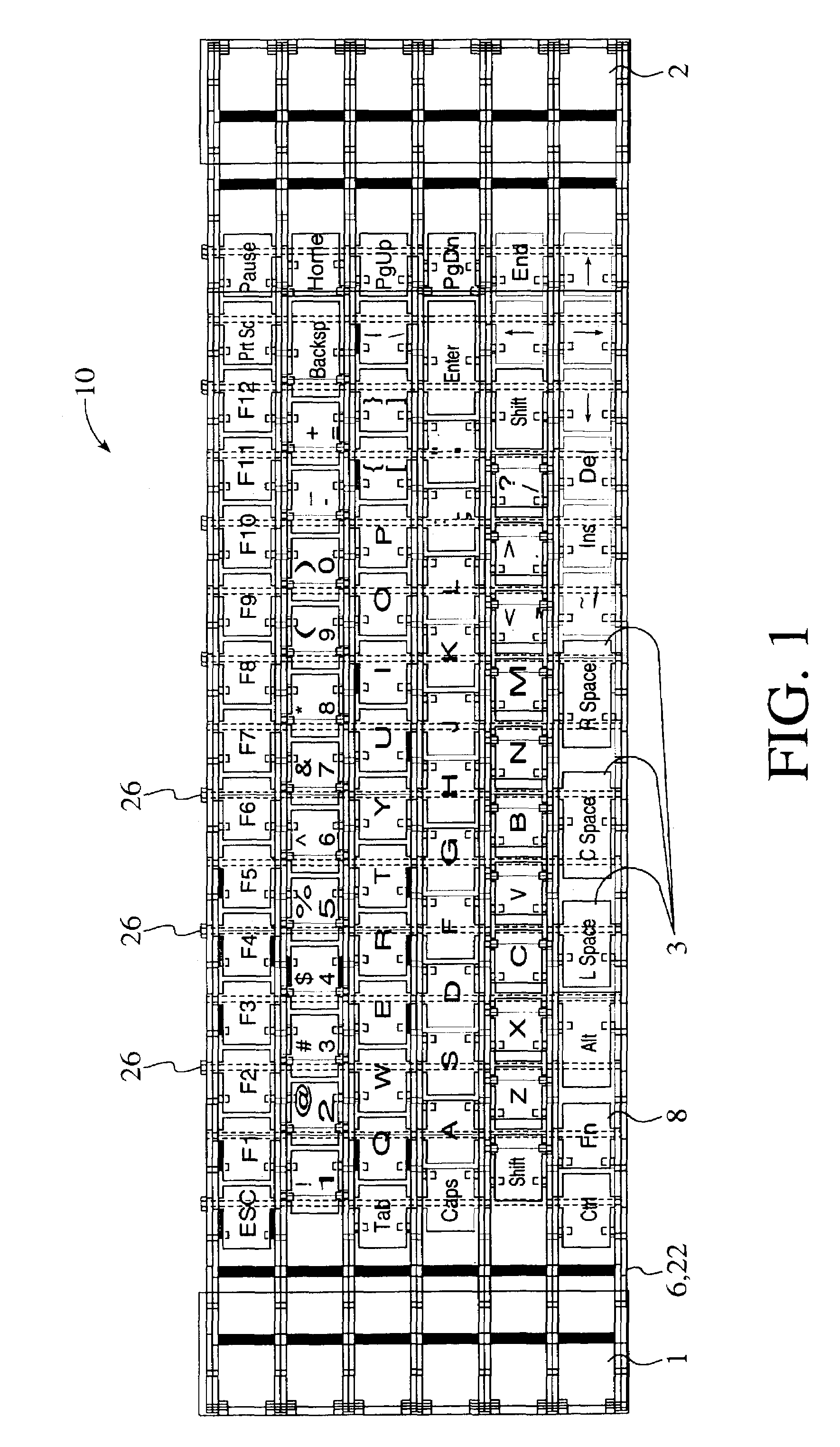
[0086]FIG. 1 shows a planar top view of an embodiment of the keyboard assembly of the invention. For convention, the rows of keys are numbered I through VI, with Row I being closest to the user or the front of the keyboard assembly. Row I includes the “Ctrl” key and row VI includes the “Pause” key. The “front” side of a key ...


PUM


Abstract

A system and method for detecting key actuation in a keyboard assembly, which, in one embodiment, is used as a conductor to electrically communicate with an information appliance. The rows in the keyboard assembly are electrically isolated from one another, and each row contains keys bridging a two-wire bus. Each key has a switch that is closed during key actuation, a diode to polarize the key, and a resistor to provide a resistive load when the switch is closed and the diode is biased with the current flow. Alternatively, each key has a switch that is closed during key actuation, a timer with an output that goes high after a predetermined time period, and a resistor that provides an identifying load when the switch is closed and the output of the timer is high. Other features of the invention include a linear matrix coupled to a row of keys to allow the row to be scanned by sections and individual keys, and a flexible circuit that provides the electrical pathways for the linear matrix.

Description

[0001]This application is a divisional application of U.S. patent application Ser. No. 09 / 191,067, which was filed on Nov. 12, 1998, now U.S. Pat. No. 6,563,434, which is a continuation-in-part of U.S. Provisional Patent Application No. 60 / 065,181, which was filed on Nov. 12, 1997; this application claims the benefit of the provisional's filing date under 35 U.S.C. § 119(e). This present application hereby claims the benefit of these earlier filing dates under 35 U.S.C. § 120.BACKGROUND OF THE INVENTION[0002]1. Field of the Invention[0003]The invention relates generally to systems and methods for detecting key actuation in keyboard assemblies for information devices, and more particularly to systems and methods for detecting key actuation in keyboards for such devices.[0004]2. Background Information[0005]Small portable computers or “palmtops” can be conveniently carried in a purse or coat pocket. Recent advances in shrinking the size of electronic components will soon allow these de...

Claims


Application Information

Patent Timeline
Patent Type & Authority Patents(United States)
IPC IPC(8): H03K17/94H03M11/00G06F1/16G06F3/02G06F3/023H03M11/20
CPCG06F1/1613G06F1/1666G06F3/0221G06F3/023H03M11/20H01H13/86H01H3/125H01H2223/05H01H2223/052
Inventor OLODORT, ROBERTTANG, JOHNTURCHIK, RANDY
Owner CALLAHAN CELLULAR L L C
Why Eureka
Try Eureka