Density range control in a photograph by variation of hue density range of the negative

Active Publication Date: 2006-08-01
NELSON MARK
View PDF16 Cites 2 Cited by
  • Summary
  • Abstract
  • Description
  • Claims
  • Application Information

AI Technical Summary

Benefits of technology

[0015]Among the many objectives of this invention is the provision of a negative density range control system by hue variation for contact printing photographic images.
[0016]A further objective of this invention is the provision of a negative density range control system using a color chart to determine the proper hue.
[0017]Yet a further objective of this invention is the provision of a negative density range control system to print pictures.
[0018]A still further objective of this

Problems solved by technology

Since the sun is such an intense light source, use of such a high intensity light requires these early processes to be slow reacting or take a relatively long exposure time to render a positive image with a full tonal scale.
The heavy demand for platinum by the arms industry, during World War I for example, causes a dramatic rise in the cost of platinum and makes the process too expensive for the average commercial photographer.
The problem with current dig

Method used


Image

  • Density range control in a photograph by variation of hue density range of the negative
  • Density range control in a photograph by variation of hue density range of the negative
  • Density range control in a photograph by variation of hue density range of the negative

Examples


Embodiment Construction

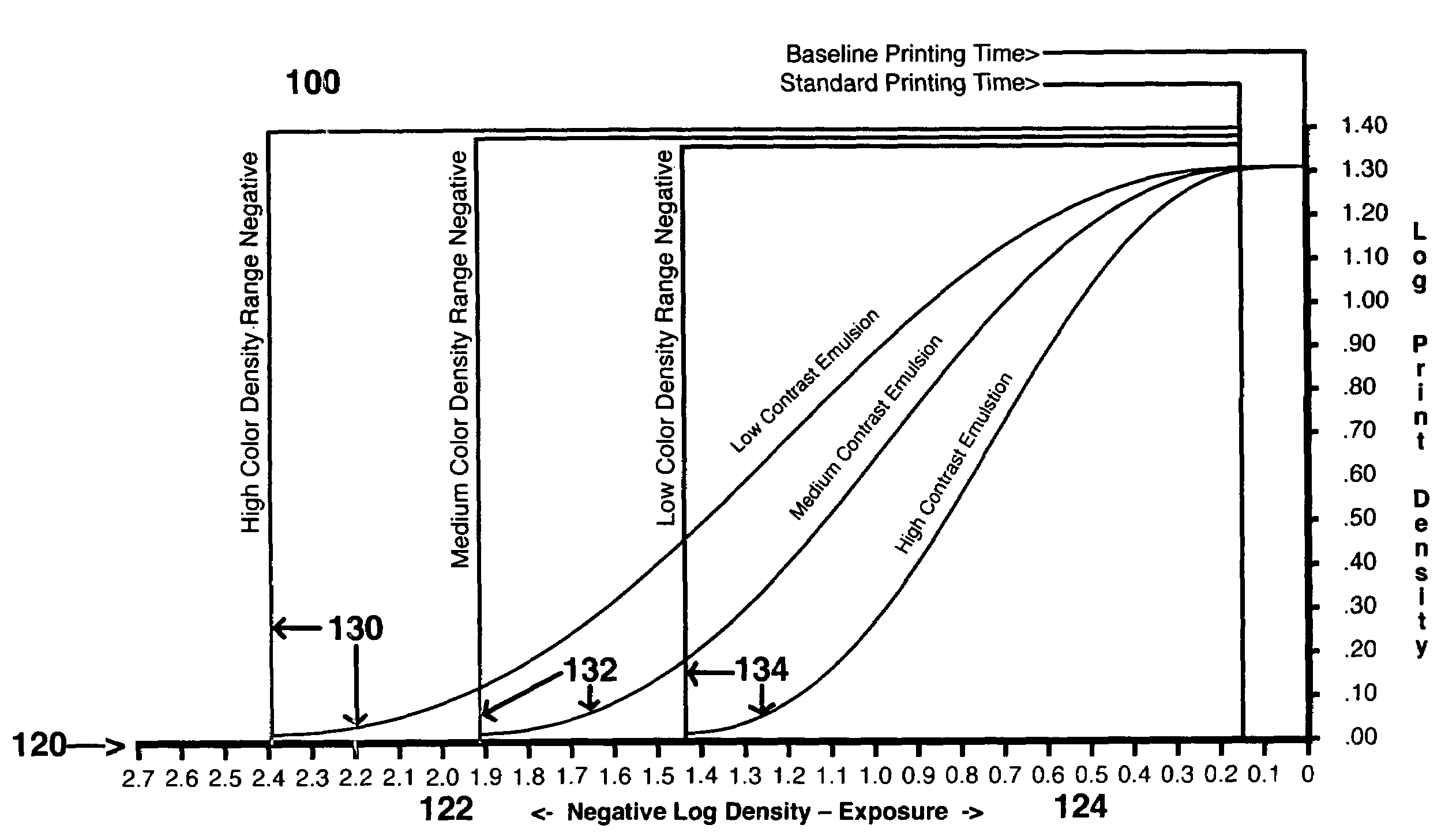
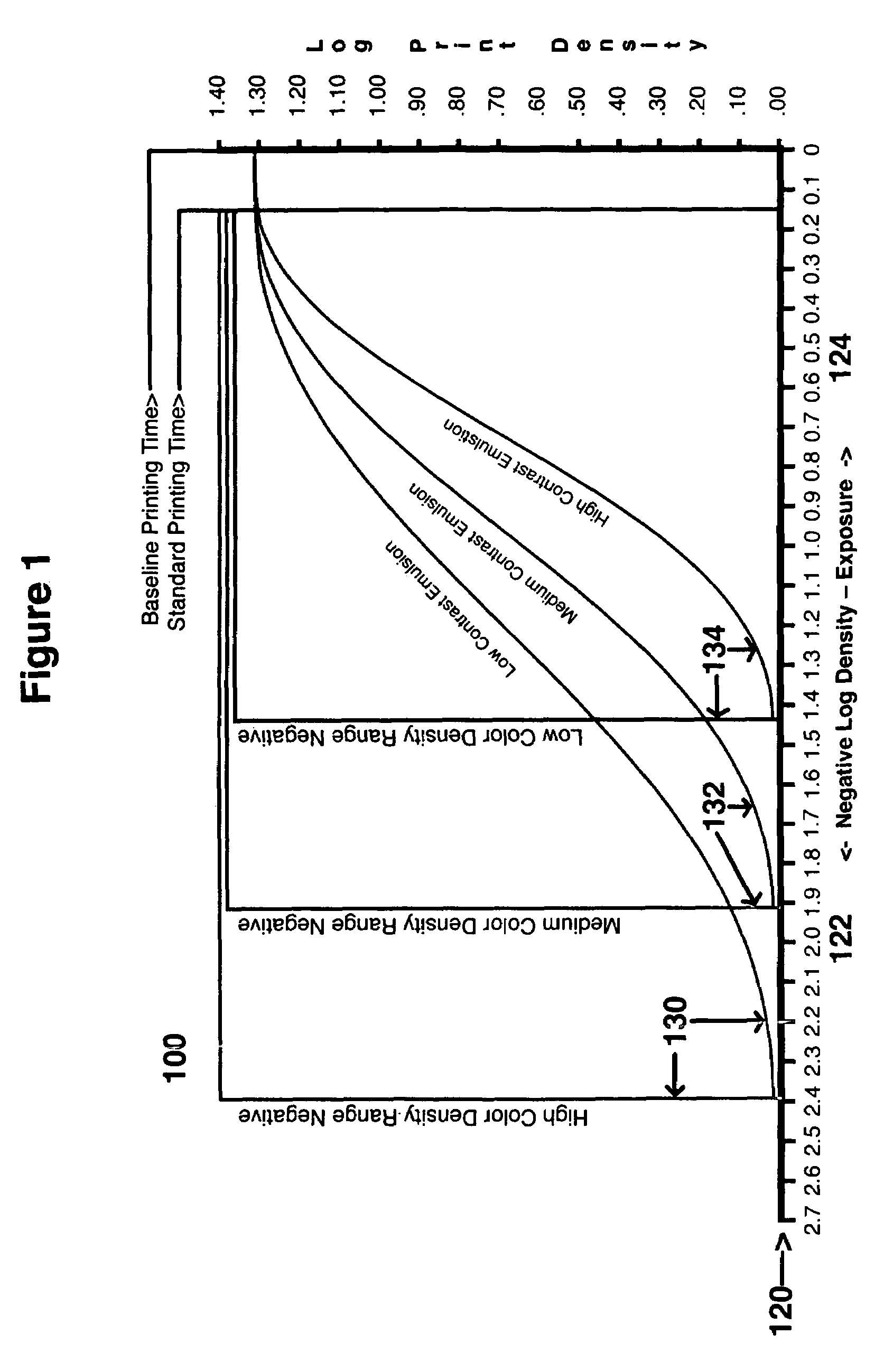
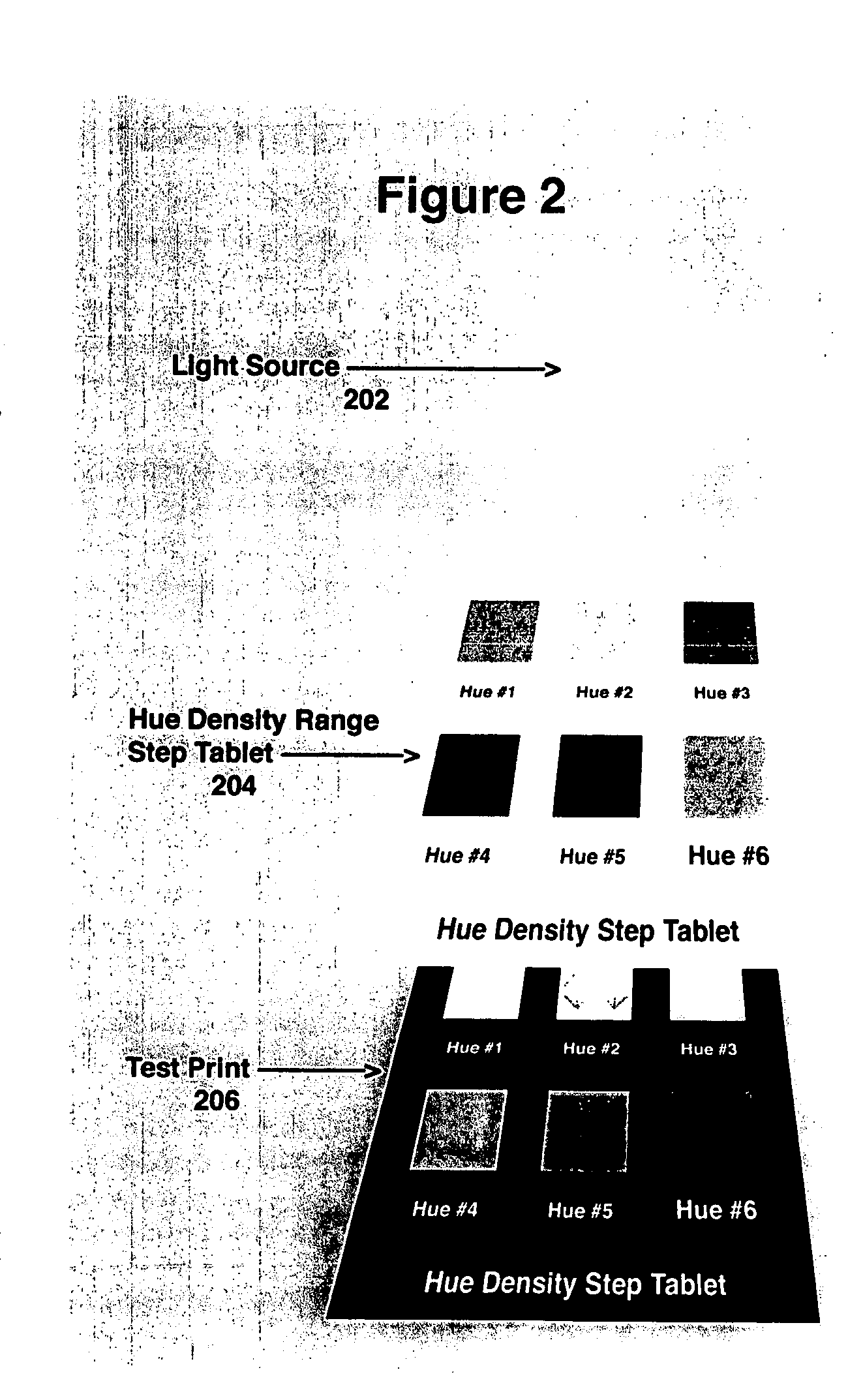
[0027]To achieve negative density range control by hue variation for contact printing photographic images, and the use of hue variation in the control of density range of direct exposure, in order to render a positive image on monochromatic papers and printing plates creates a greatly improved process for providing negatives or pictures. By hue is meant the color of the negative in contact printing or the color of light in direct exposure of positives. Color and hue may be used interchangeably herein.

[0028]The solution for better digital negatives controls negative density ranges. The method of controlling digital negative density ranges of this invention works with any of the 19th century processes and any modern processes that can be exposed by a Contact Printed Negative.

[0029]Instead of using the Curve Function to adjust the density range of the image negative, a far better negative can be made by converting the black and white negative image to a hue or color that prints with th...


PUM


Abstract

A negative density range control system uses color hue contrast to provide a print of a picture, by comparing the relationship between negative hue density and print emulsion density requirement and providing an appropriate density for a printing process, whether converting a positive digital image to negative digital image with a specific hue density color or making a print by contact printing a hue density negative rendered from a digital image file.

Description

[0001]This invention relates generally to negative contrast control by hue variation and more particularly, to negative contrast control system by hue variation of a density range for contact printing photographic images and the use of hue variation of direct exposure, in order to render a positive image on monochromatic papers and printing plates.BACKGROUND OF THE INVENTION[0002]For the period of the nineteenth century, with photography beginning to come on the scene, all photographic images are printed by contact printing. Cameras for that time make “negatives” on coated glass plates or paper. This negative is then placed on top of a paper coated with a light-sensitive emulsion and Contact Printed using sunlight. The resulting positive print will be the exact size of the original negative.[0003]During the early years of photographic history, the only light source available for contact printing is the sun. Since the sun is such an intense light source, use of such a high intensity ...

Claims


Application Information

Patent Timeline
IPC IPC(8): G03B33/00G06K15/12
CPCG03B33/00
Inventor NELSON, MARK
Owner NELSON MARK
Why Eureka
Try Eureka