Adjustable measuring scoop

a technology of measuring scoops and scoops, which is applied in the direction of instruments, spades, liquid/fluent solid measurement, etc., can solve the problem that the adjustment of both devices requires a relatively long manual motion to move, and achieves the effect of convenient manual adjustment, effective implementation, and convenient manual adjustmen

Active Publication Date: 2006-08-08
DALLA PIAZZA
View PDF26 Cites 18 Cited by
  • Summary
  • Abstract
  • Description
  • Claims
  • Application Information

AI Technical Summary

Benefits of technology

[0004]The present invention is directed to an adjustable measuring scoop that may address one or more of the foregoing and / or other prior art shortcomings. An adjustable measuring scoop according to the present invention includes a movable partition that adjustably rotates on a rotating means such as an axle so as to result in a scoop size that can be selectively determined between a maximum and a minimum by ready manual manipulation of the scoop by a user. In one aspect of the invention, the movable partition and rotating means are preferably configured so that the movable partition moves toward and away from the scoop's opening, permitting, inter alia, a symmetric frontal contour that may be more effective in scooping an ingredient, for example, from the bottom region of a container. In another optional separate aspect of the invention, adjustment of the movable partition is effected by operation of means including a manual slide that has a range of motion that is linear rather than arcuate, so as to permit more convenient manual adjustment. In yet another separate optional aspect of the invention, adjustment of the movable partition is effected by operation of means including a lever having a range of motion that is short relative to the resulting movement of the movable partition, so as to permit more convenient manual adjustment. In still another separate optional aspect of the invention, the movable partition may be effectively implemented without the need for an accompanying covering portion, permitting a design in which scooping with and / or cleaning of the device may be cleaner and / or easier.

Problems solved by technology

Additionally, adjustment of both devices requires a relatively long manual motion to move from the minimum to maximum positions.

Method used


Image

  • Adjustable measuring scoop
  • Adjustable measuring scoop
  • Adjustable measuring scoop

Examples


Embodiment Construction

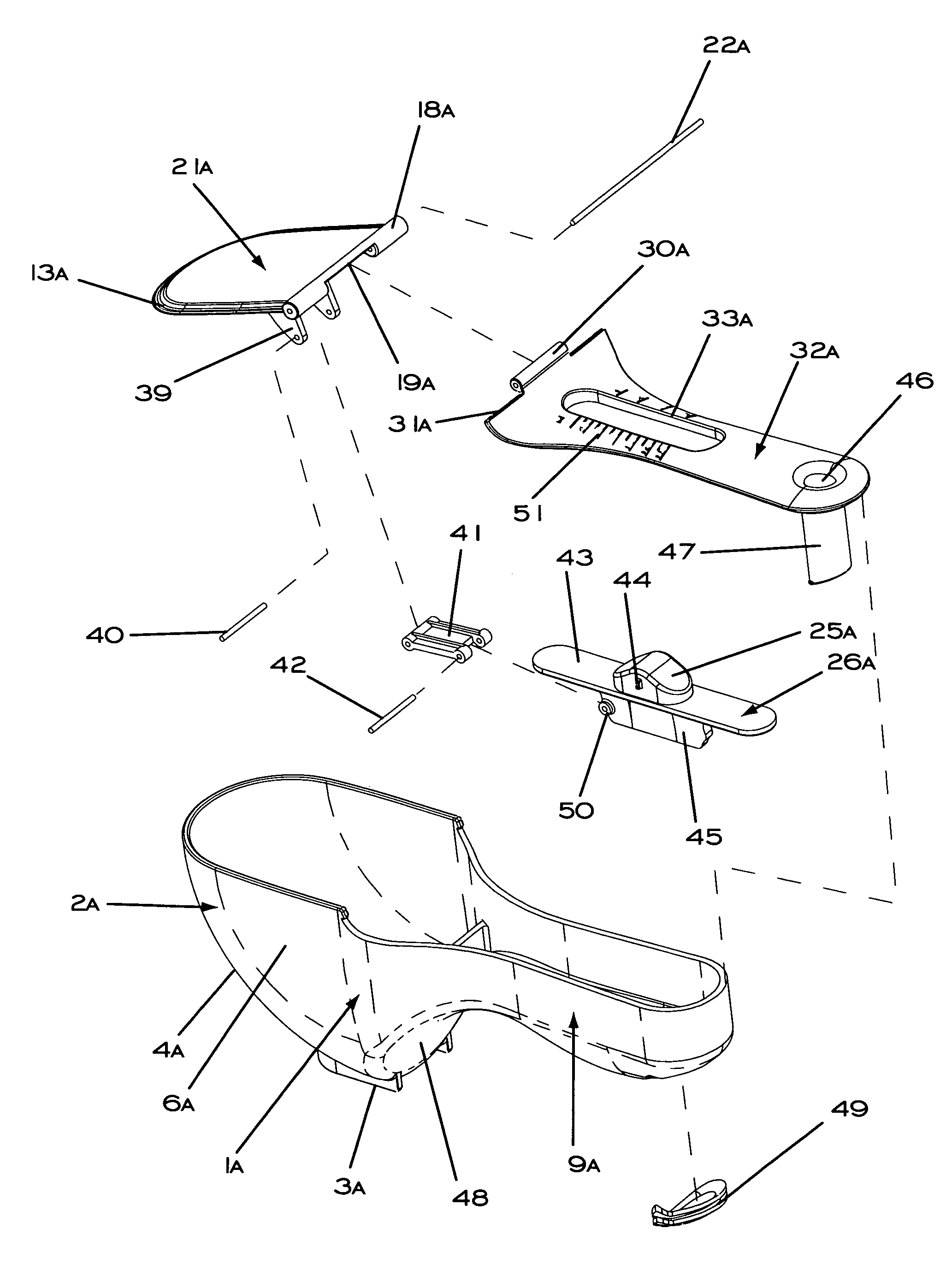
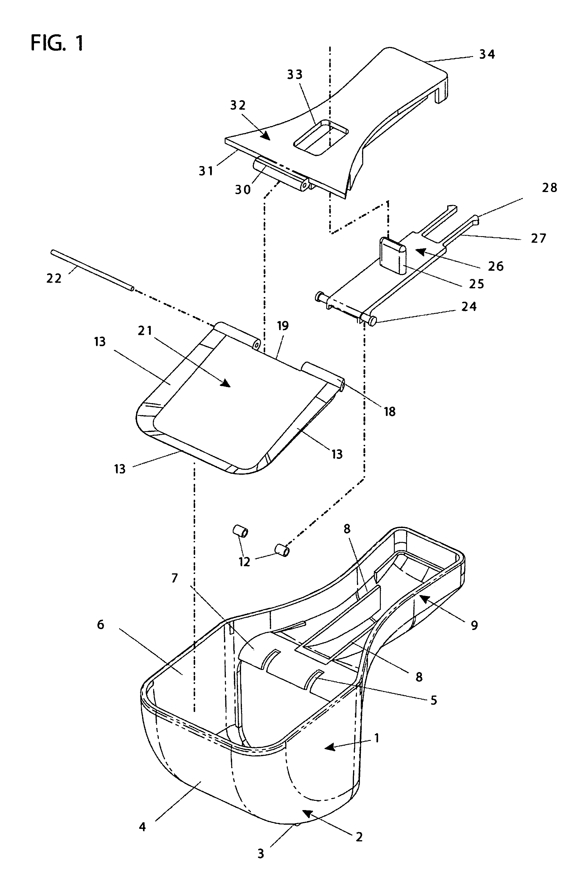
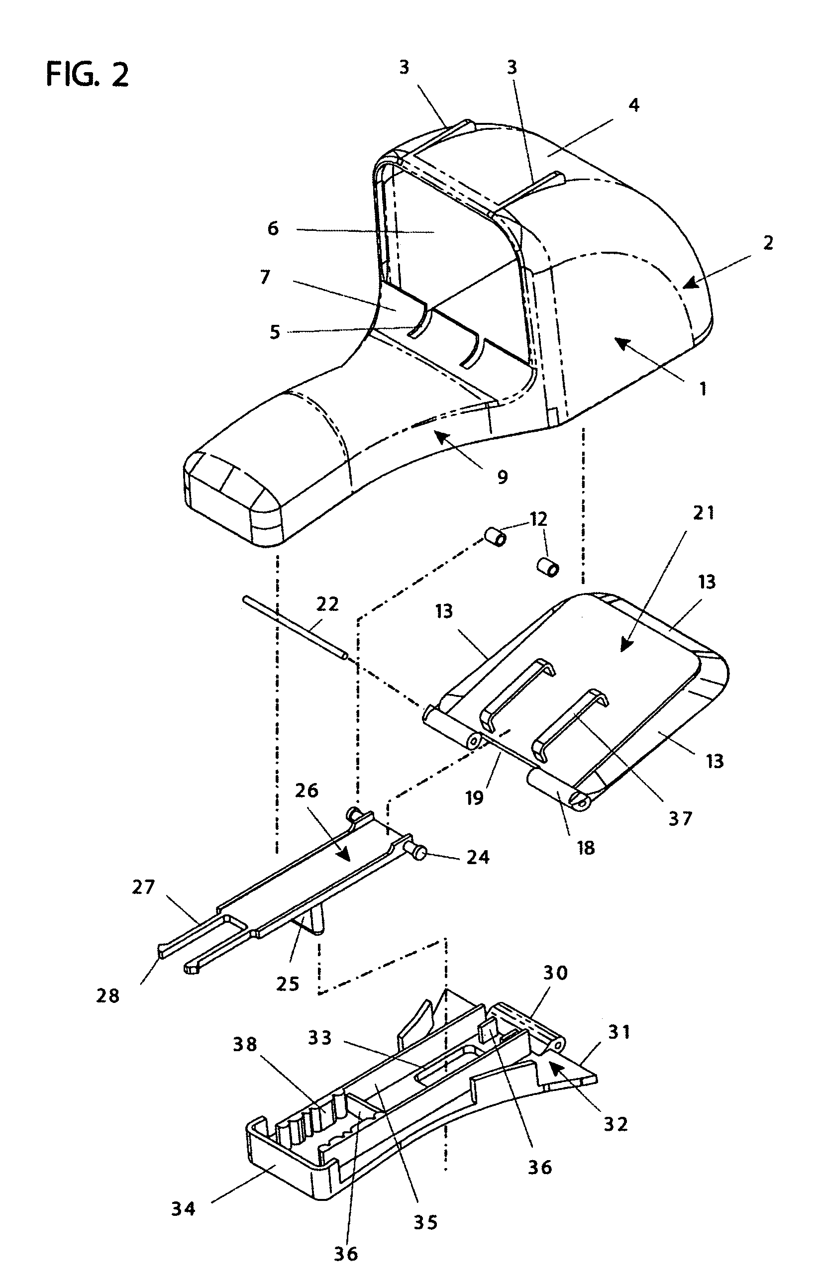
[0016]A first preferred embodiment of an adjustable measuring scoop according to the invention is shown in FIGS. 1–6. Scoop 1 is a utensil preferably used for measurement of quantities of materials such as cooking ingredients or any other suitable items. The capacity of scoop 1 is adjustable to allow measurement of a range of quantities of materials. Scoop 1 is preferably made predominantly of molded plastic although other materials such as metal or aluminum can be used.

[0017]Scoop 1 generally comprises a bucket 2, an ergonomically shaped handle 9, and a movable partition 21. The walls of the bucket 2 comprise a front / bottom portion 4 and side portions 6, with pedestals 3 provided at the bottom of front / bottom portion 4 to permit the scoop to be rested on a suitable flat surface. The handle 9 also includes a finger rest 7 provided with two guide slots 5, and the movable partition 21 includes a lip 13 along its perimeter that snugly contacts the interior of the walls of bucket 2.

[001...


PUM


Abstract

An adjustable measuring scoop including a movable partition that adjustably rotates on a rotating means such as an axle so as to result in a scoop size that can be selectively determined between a maximum and a minimum by ready manual manipulation of the scoop. The movable partition and rotating means are preferably configured so that the movable partition moves toward and away from the scoop's opening, permitting, e.g., a symmetric frontal contour that may be more effective in scooping from a container. Adjustment of the movable partition may also optionally be effected by means including a manual slide that has a linear and / or relatively short range of motion.

Description

RELATED APPLICATION[0001]This application is a continuation-in-part of U.S. patent application Ser. No. 10 / 765,294 entitled “Adjustable Measuring Scoop,” and filed on Jan. 27, 2004.FIELD OF THE INVENTION[0002]The present invention generally relates to the field of measuring devices, and more particularly to a measuring scoop that can be adjusted to measure various specific amounts of materials such as cooking ingredients.BACKGROUND OF THE INVENTION[0003]Adjustable measuring devices exist, but with one or more drawbacks. U.S. Pat. No. 5,678,450 to Robbins et al. discloses an adjustable measurement container in which the size of the scoop is adjusted by linearly sliding a sliding member that includes a covering portion (unnumbered) and a partition (dam 42). U.S. Pat. No. 6,125,699 to Molenaar discloses an adjustable measuring spoon in which the size of the scoop is adjusted by rotating a pivoting member that also includes a covering portion (gate 23) and a partition (49). Use and / or c...

Claims


Application Information

Patent Timeline
Patent Type & Authority Patents(United States)
IPC IPC(8): G01F19/00A01B1/02A47F13/08
CPCG01F19/002A47F13/08
Inventor KILDUFF, EDWARD H.KANG, WILLIAM Y.
Owner DALLA PIAZZA
Why Eureka
Try Eureka