Coaxial connector

a technology of coaxial connectors and connectors, which is applied in the direction of coupling device connections, scaffold accessories, building scaffolds, etc., can solve the problems of plugs falling off, troublesome assembly of receptacles, and unsatisfactory high-frequency performance, and achieve satisfactory high-frequency performance, satisfactory high-frequency performance, and satisfactory high-frequency performan

Inactive Publication Date: 2006-08-08
HIROSE ELECTRIC GROUP
View PDF8 Cites 49 Cited by
  • Summary
  • Abstract
  • Description
  • Claims
  • Application Information

AI Technical Summary

Benefits of technology

[0015]Accordingly, it is a first object of the invention to provide a coaxial connector, which can be assembled easily, enables complete shielding of the inner conductor, and can achieve satisfactory high-frequency performance.
[0016]It is a second object to provide a coaxial connector, which can achieve satisfactory high-frequency performance even without the backside shielding.

Problems solved by technology

Since there is no outer conductor at the lead sections 84a and 85a of the connecting terminal 84 and the switching terminal 85, there is a problem of unsatisfactory high-frequency performance due to lack of shielding.
However, the thickness of the cylindrical section of the plug is small and the cylindrical section is not strong enough and has weak locking ability, so that there is a problem that the plug comes off when the plug often receives external force.
Therefore, it has been troublesome to assemble the receptacle 104.

Method used


Image

  • Coaxial connector
  • Coaxial connector
  • Coaxial connector

Examples


first embodiment

[0080]The first embodiment of the coaxial connector of the invention is shown in FIGS. 1–15.

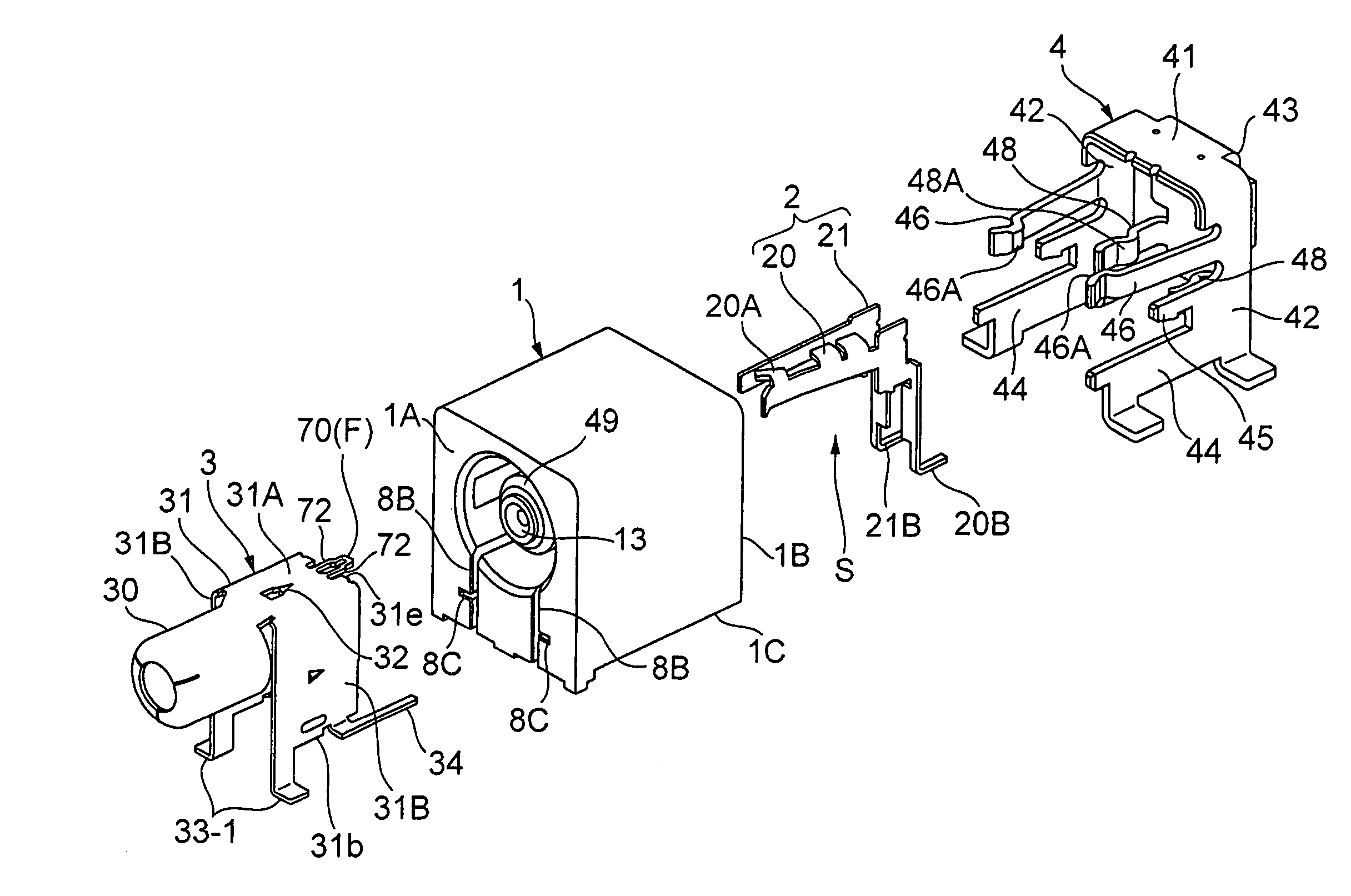
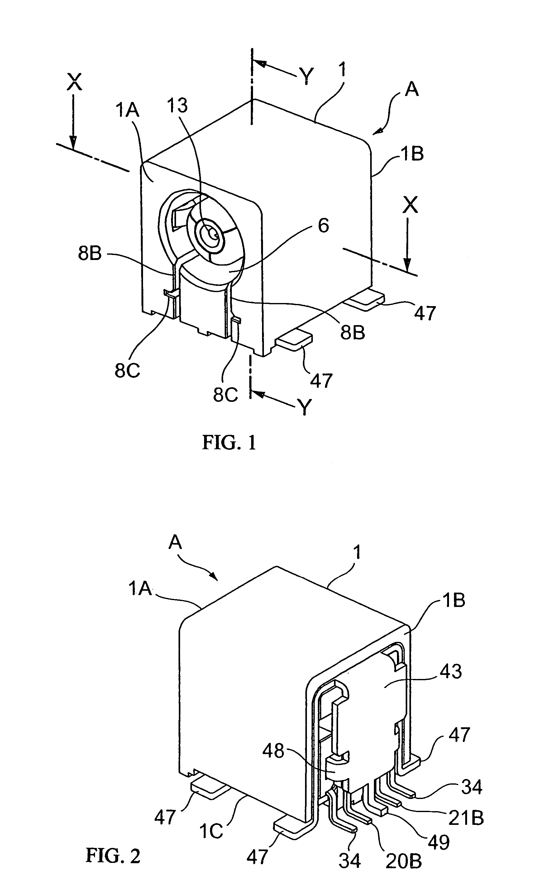
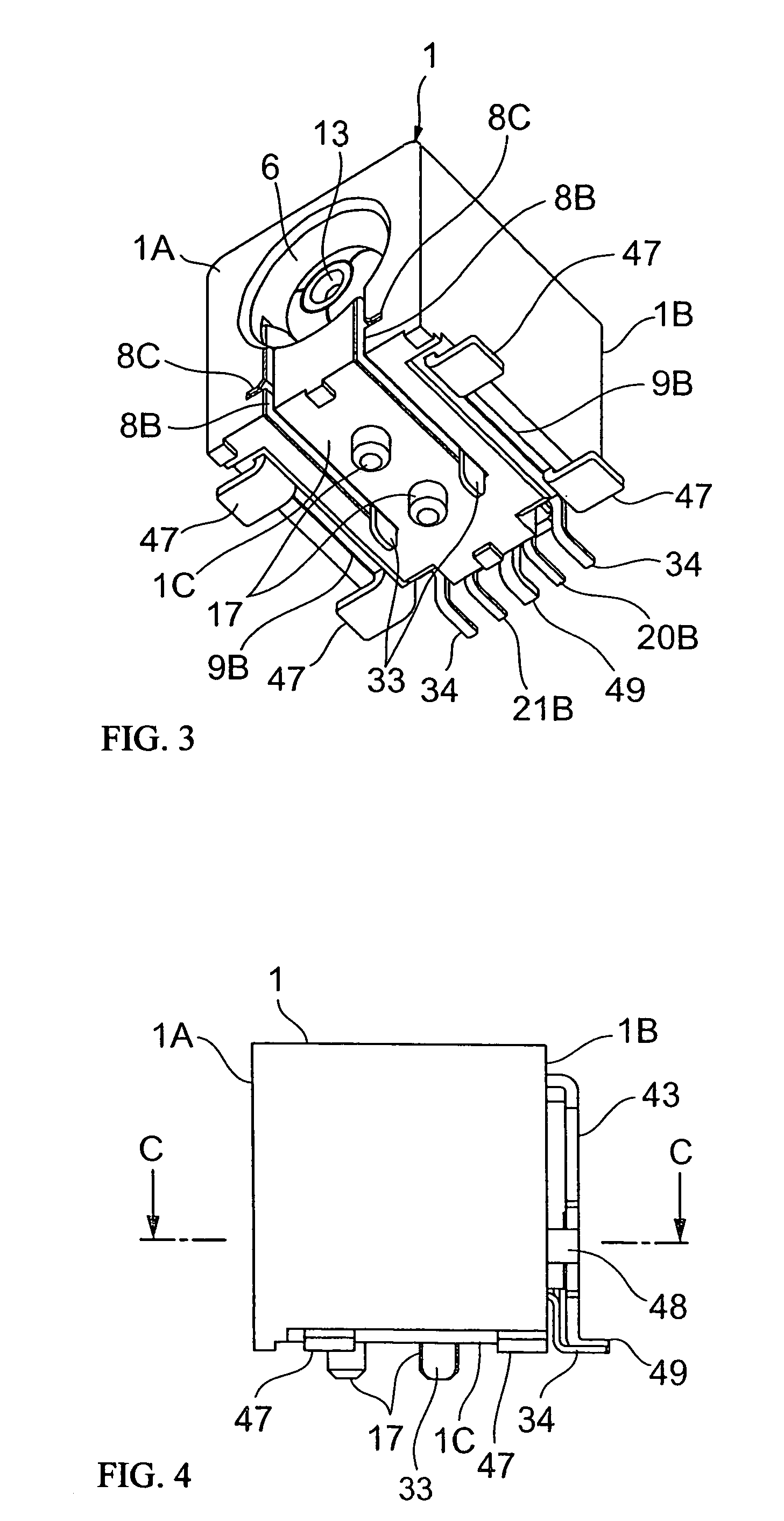
[0081]The receptacle A, which is the coaxial connector of the invention, is to join to a plug B, which is the counter connector. As shown in FIG. 5, the receptacle A is comprised of an insulating housing 1, an inner conductor 2, and a first and a second outer conductors, which constitutes an outer conductor.

[0082]As shown in FIGS. 7 and 8, the insulating housing 1 has an inner housing section 5, and a counter connector fitting concave section 6 provided to surround the inner housing 5. An inner conductor attaching section 7 is formed at the center portion of the inner housing section 5. In addition, a first and a second outer conductor attaching sections 8 and 9 are formed so as to surround the inner conductor attaching section 7.

[0083]As shown in FIGS. 3, 5, and 7–9, the first outer conductor attaching section 8 is formed from the front section 1A toward the backside section 1B of the insula...

second embodiment

[0113]The second embodiment of the coaxial connector of the invention is shown in FIGS. 16–24. Here, similar elements to those in the first embodiment are denoted by the same referential numerals, and the explanation is omitted.

[0114]In the second embodiment of the invention, the contact means to contact the first outer conductor 3 with the second outer conductor 4 is formed by contacting the pair of contact sections 48 of the backside shielding section 43 of the second outer conductor 4 with the side shielding section 31B (side portion of the first outer conductor 3); and contacting the edge shielding section 31A of the first outer conductor 3 with the backside shielding section 43 via a conductive contact means F.

[0115]More specifically, as shown in FIGS. 16–17, the conductive contact section F has a contact shoe 70, which is provided at the center of the edge 31e of the edge shielding section 31A of the first outer conductor 3, which faces the second outer conductor 4, so as to p...

third embodiment

[0134]The third embodiment of the coaxial connector of the invention is shown in FIGS. 30–32.

[0135]The difference of the third embodiment from the above-described first embodiment is that the second outer conductor 4-1 of the third embodiment does not have the backside shielding section 43, and the contact section 48 and the lead section 49 provided on the backside shielding section 43.

[0136]Accordingly, the contact between the pair of contact sections 48 of the backside shielding section 43 and the side shielding section 31B of the first outer conductor 3 is not made. In addition, the contact of edges of the edge shielding section 31A of the first outer conductor 3 and the side shielding section 31B with the inner surface of the backside shielding section is not made. Also, the contact between the first outer conductor 3 and the second outer conductor 4 is not made.

[0137]The constitution and operation of the third embodiment are same as those of the first embodiment except the cont...


PUM


Abstract

The outer conductor is comprised of a first outer conductor (3) and a second outer conductor (4). The first outer conductor (3) and the second outer conductor (4) are connected to each other by attaching them to an insulating housing (1) and contacting the contact section (48) of the second outer conductor (4) to the first outer conductor (1). The backsides of the switching terminal (20) and the connecting terminal (21) are covered by a backside shielding section (43), and the lead section provided on the backside shielding section (43) is arranged between the lead section (20B) of the switching terminal (20) and the lead section (21B) of the connecting terminal (21).

Description

BACKGROUND OF THE INVENTION[0001]The present invention relates to a coaxial connector having a switch, which is loaded in an information terminal device, such as a cellular phone, and used in input / output unit of such a device.[0002]As shown in FIG. 33, a receptacle 80 of a conventional coaxial connector having a switch has an insulating housing 81, and a fitting convex section 82, which is formed at the insulating housing 81. A terminal attaching hole 83 is provided at the center portion of the fitting convex section 82. A connecting terminal 84 and a switching terminal having a contact section 85a are attached to the terminal attaching hole 83. A break contact point section 84a of the connecting terminal 84 contacts with the switching terminal 85. An outer conductor (shell) 86 is attached to the insulating housing 81, and a cylindrical section 87 of the outer conductor 86 covers the fitting convex section 82.[0003]The receptacle80 with the above-described constitution is mounted o...

Claims


Application Information

Patent Timeline
Patent Type & Authority Patents(United States)
IPC IPC(8): H01R12/00H01R13/71
CPCH01R24/42Y10S439/944H01R2103/00E04G3/00E04G5/04E04G5/06E04G5/08E04G5/14E04G5/16
Inventor NAKAGAWA, TSUYOSHIOZAKI, TETSUYA
Owner HIROSE ELECTRIC GROUP
Why Eureka
Try Eureka