
Jack

a technology of jacks and contacts, applied in the direction of coupling contact members, coupling device connections, coupling/insulating coupling contact members, etc., can solve the problems of difficult insertion of plugs b>65/b>, and achieve the effect of eliminating the causes of connection failure and good electroconductivity

Inactive Publication Date: 2006-08-08
JST MFG CO LTD
View PDF13 Cites 21 Cited by
  • Summary
  • Abstract
  • Description
  • Claims
  • Application Information

AI Technical Summary

Benefits of technology

The solution provides a secure and stable connection, preventing deflection of the hollow columnar contact and ensuring reliable electrical transmission, while allowing for easy removal and assembly without applying mechanical force to electrical connections.

Problems solved by technology

Furthermore, as illustrated in the sectional view of FIG. 17C, the insertion of the plug 65 may be made difficult.

Method used


Image

  • Jack
  • Jack
  • Jack

Examples


Embodiment Construction

[0065]The preferred embodiment of the present invention will be described below in reference to the drawings. However, the present invention is not limited to the embodiment, and various modifications and changes in design can be made without departing from the scope of the invention.

[0066]In regard to the embodiment, since this invention's jack is equipped with a hollow columnar contact and a J-shaped contact, a contact insertion chamber, into which the hollow columnar contact is inserted, shall be referred to as a “first insertion chamber” and a contact insertion chamber, into which the J-shaped contact is inserted, shall be referred to as a “second insertion chamber” to distinguish between the two in the following description.

[0067]Also, a contact insertion opening, which is to be an opening of the “first insertion chamber,” shall be referred to as a “first opening” and a contact insertion opening, which is to be an opening of the “second insertion chamber,” shall be referred to ...


PUM


Abstract

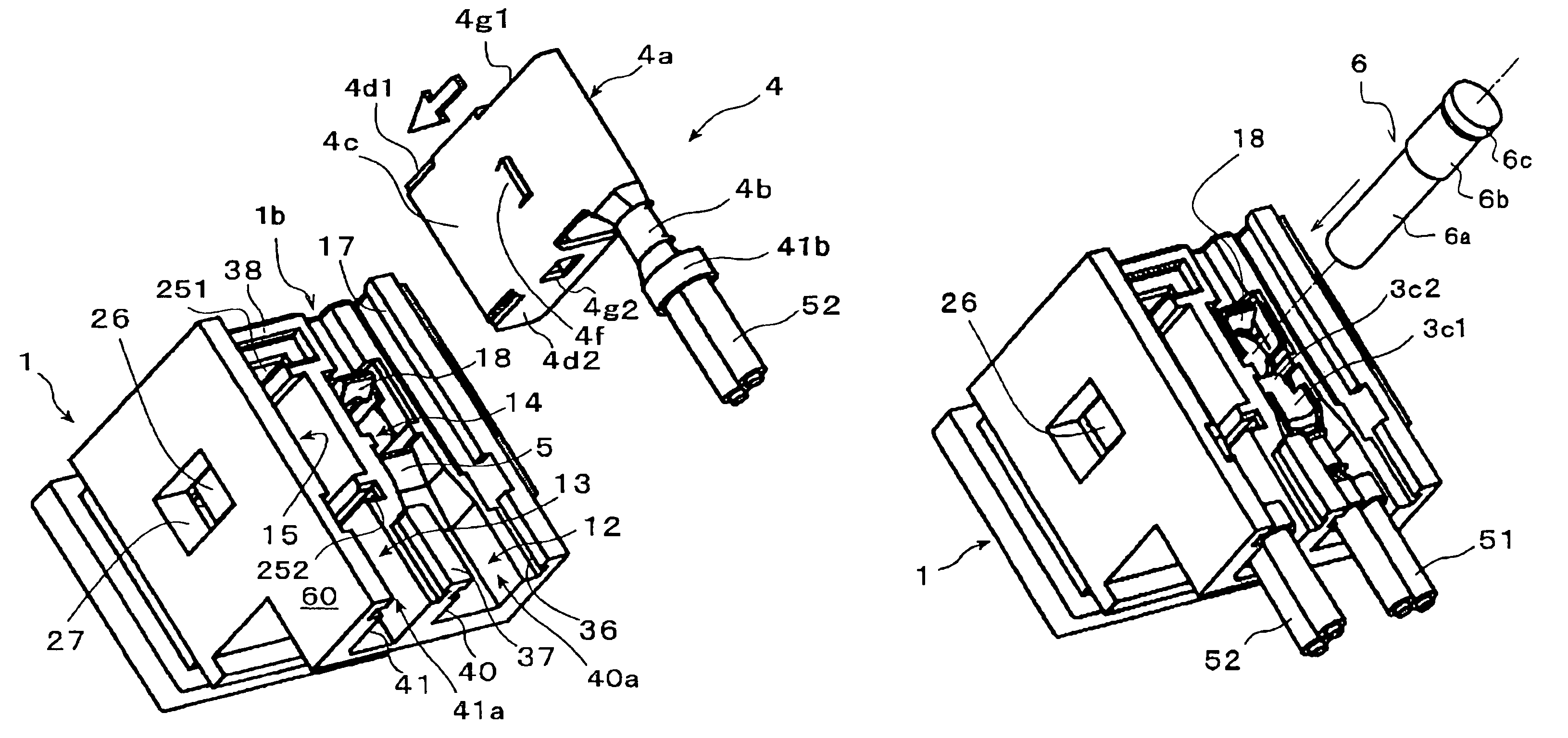
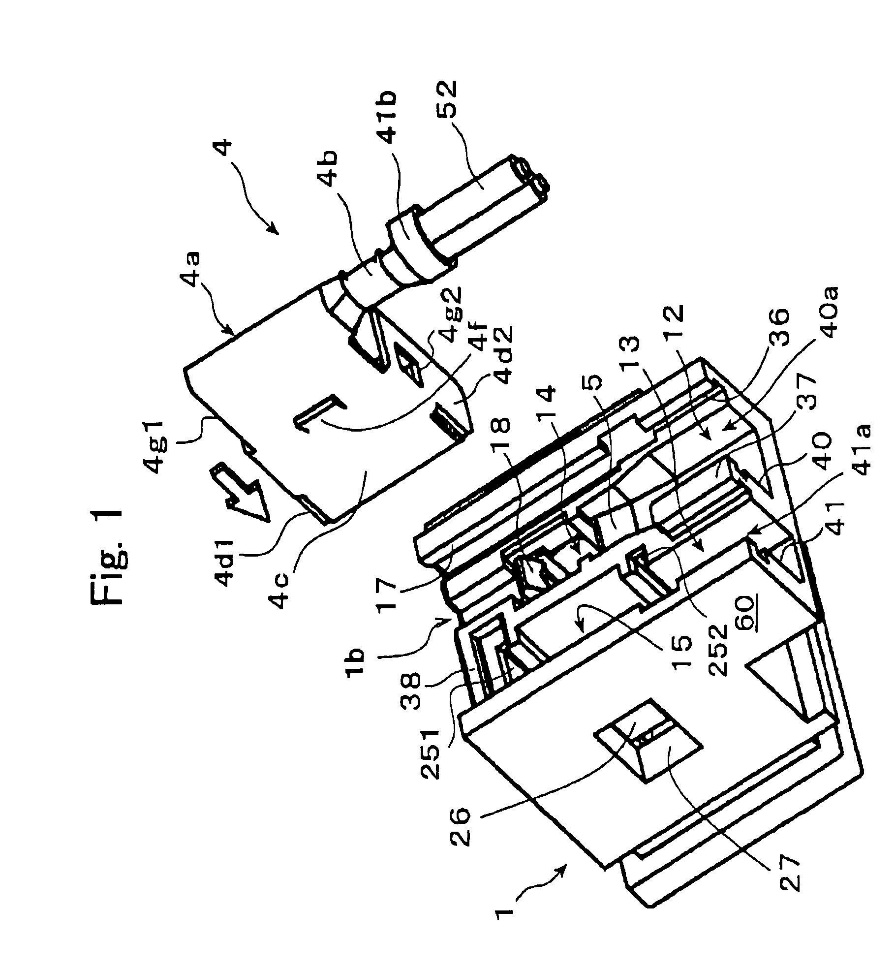
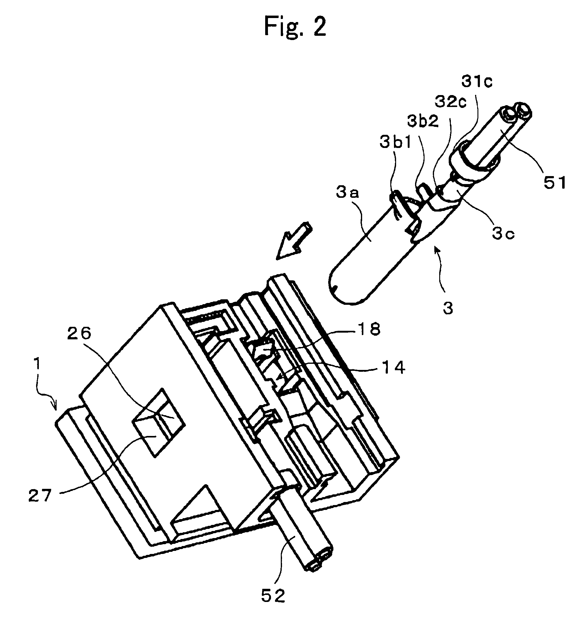
A jack with a hollow columnar contact has a housing, which holds the hollow columnar contact firmly and the front end of the hollow columnar contact does not deflect readily. The insulating housing 1 comprises a plug connection opening 61, which a mating plug 65 is inserted into, a first insertion chamber 9 having the plug connection opening 61, and a first opening 14 in communication with the contact insertion chamber 9. The hollow columnar contact 3 is inserted along an axial direction into the first insertion chamber from the first opening 14. A cylindrical main contact body 3a is held by the first opening 14. A press-fit pin 6, arranged with a small-diameter axial part 6a, a large-diameter axial part 6b, and a head part 6c having an outer diameter is press-fitted into the cylindrical main contact body 4a.

Description

CROSS-REFERENCE TO RELATED APPLICATIONS[0001]This application is based upon and claims the benefits of priorities from Japanese Patent Application No, 2004-027307 filed on Feb. 3, 2004, the entire contents of which are incorporated herein by reference.FIELD OF THE INVENTION[0002]The present invention relates to a jack to be used for transmitting electrical signals or energy in a notebook personal computer or other portable electronic equipment and particularly relates to the structure of a housing and contacts, etc., employed in such a jack.RELATED ART[0003]Portable electronic equipments operate on DC in many cases, and AC adapters are used to step down and, at the same time, convert the voltage of a household AC power supply to DC to provide power for portable electronic equipments. In many cases, a cable with plug is used as an AC adapter, and this plug is inserted into and electrically connected to a DC power supply jack provided with a portable electronic equipment to supply DC ...

Claims


Application Information

Patent Timeline
Patent Type & Authority Patents(United States)
IPC IPC(8): H01R24/04H01R4/16H01R13/42H01R13/447
CPCH01R13/42H01R4/16H01R13/447
Inventor FUKUZAKI, HIROSHIKIHIRA, SATORUWASHINO, KIYOSHIFUKAMI, TSUYOSHIMORITA, YUKITAKAI, MASAHARU
Owner JST MFG CO LTD
Learn More