Apparatus and process for downflow fluid catalytic cracking

a technology of fluid catalytic cracking and apparatus, which is applied in the direction of lighting and heating apparatus, furnace types, furnaces, etc., can solve the problems of longer catalyst residence time, significant slow catalytic flow, and difficult separation, so as to improve the overall process performance and quick and easy separation

Active Publication Date: 2006-08-08
PETROLEO BRASILEIRO SA (PETROBRAS)
View PDF17 Cites 24 Cited by
  • Summary
  • Abstract
  • Description
  • Claims
  • Application Information

AI Technical Summary

Benefits of technology

[0034]Thus, the present invention provides an apparatus for FCC downflow reactions which combines a regenerated catalyst riser which lifts a diluted phase catalyst phase up to a catalyst distributor the design of which, combined to the features of the feed injectors, connected through a properly designed catalyst acceleration zone, allows an optimum catalyst-to-oil mixing.
[0035]The present invention provides still an apparatus for FCC downflow reactions which permits quick and easy separation of spent catalyst and reacted hydrocarbons, further improving overall process performance.
[0036]The present invention provides further a low-cost installation of the present apparatus in an existing FCC unit.

Problems solved by technology

Furthermore, the upward flow of solid catalyst and hydrocarbon vapor in riser reactors oppose gravity, resulting in a catalyst flow that is significantly slower than the much lighter hydrocarbon flow.
This results in backmixing of the catalyst, leading to longer residence times of the catalyst and the occurrence of undesirable secondary reactions such as overcracking.
It is alleged that in downward reactors the separation is made more difficult in virtue of the substantial concentration of catalyst in the reaction medium, which requires specifically designed equipment if suitable efficiency is to be enjoyed.
However, this arrangement implies that the contact time between hydrocarbon vapor and catalyst is made excessively long, with the ensuing well-known drawbacks resulting from long contact time, that is, thermal cracking, coke, etc.
Therefore the advantages from the use of both downflow and riser reactors may be wasted and the efficacy of the technique to secure the alleged benefits are rather low.
Also discussed in said US '369 patent is a shortcoming of the downflow reactor, that is, initial catalyst-to-oil mixing can be difficult to achieve because gravity acts to decrease the solids density in the zone of initial contacting, contrary to the effects noted in a riser.
However fluidized solids flow is never truly steady and usually features small-amplitude oscillations in solids density whether moving in a riser or a downflow reactor.
Oil, which enters in a region of low solid density will remain there through the entire reactor, ultimately subject to thermal cracking due to premature deactivation of the catalyst.
Oil in a high-density region tends to be overcracked.
However, the device taught in PI BR 0101433-1 does not allow processing a mixture of catalyst and gas.
Quick separation of hydrocarbon products and catalyst is a mandatory consequence of the short contact reaction time achieved in a downflow reactor, since it is nearly meaningless to profit from the benefits of the downflow reactor while such benefits may be lost by a too long separation step.
The problem is that discharging catalyst into separation section 15 of vessel 16 having such a high ratio of cross sectional area implies in augmented possibilities of undesirable thermal cracking and coke build-up.
Also, the concept of U.S. Pat. No. 4,514,285 does not allow to processing a mixture of catalyst and gas.
It should be pointed out that the use of enclosing cyclone separators taught by said US patent may be a problem whenever there is any unsteady operation of the reactor, which leads to a lower separator efficiency and therefore to undesirable overcracking reactions due to entrainment of the gas phase which reacted with the catalyst suspension, as well as heavy catalyst losses to the product fractioning system and auxiliary equipment thereof.
Also, U.S. Pat. No. 5,582,712 does not recognize the necessity of providing an external path for stripper gases.
This amount may cause circulation problems due to equipment fouling, loss of heat exchange capacity, pump losses due to rapid erosion, besides an extremely high catalyst operational cost.
So, a device based on cyclone separation without considering an external passage for the stripper gas or for small amounts of gas escaping from the cyclone due to pressure surges would probably suffer from an efficiency loss even much higher than that of the cited example.

Method used


Image

  • Apparatus and process for downflow fluid catalytic cracking
  • Apparatus and process for downflow fluid catalytic cracking
  • Apparatus and process for downflow fluid catalytic cracking

Examples


example

[0148]The feed is made up of 80% heavy gasoil and 20% vacuum residue. The feed main features are listed in Table 1 below.

[0149]

TABLE 1D20 / 40.9386R.C.R (wt %)0.38SULFUR (% wt)0.575ASPHALTENES (% wt)0.1TOTAL NITROGEN (ppm)3,211BASIC NITROGEN (ppm)961ANILINE POINT (° C.)80.8VISCOSITY AT 40° C. (cSt)268.4VISCOSITY AT 100° C. (cSt)14.57ASTM D 1160 DISTILLATION@ 760 mmHg, ° C.IBP334.55%387.110%398.320%423.230%440.640%455.650%471.360%490.470%512.4METALS (ppm)NiV

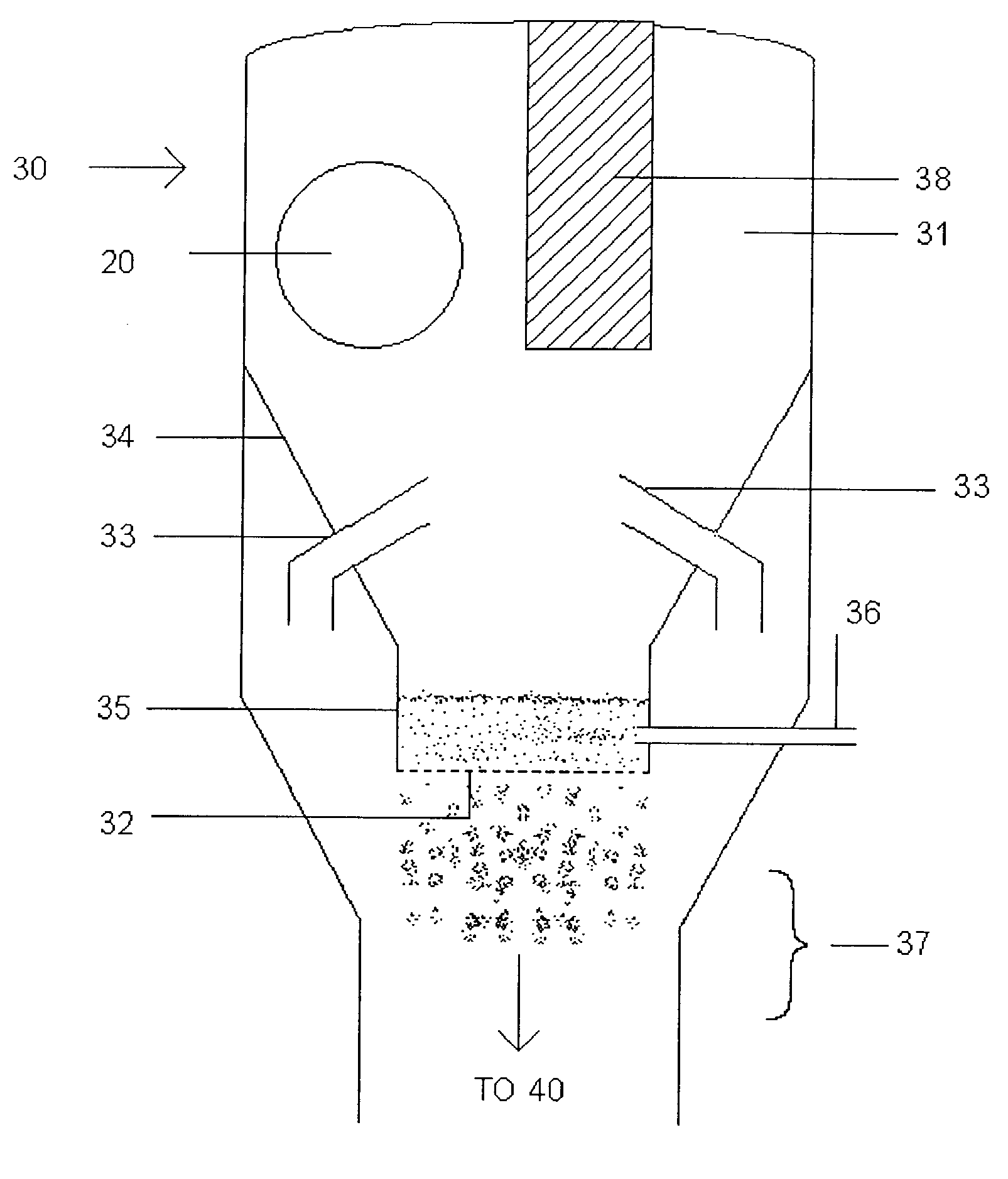
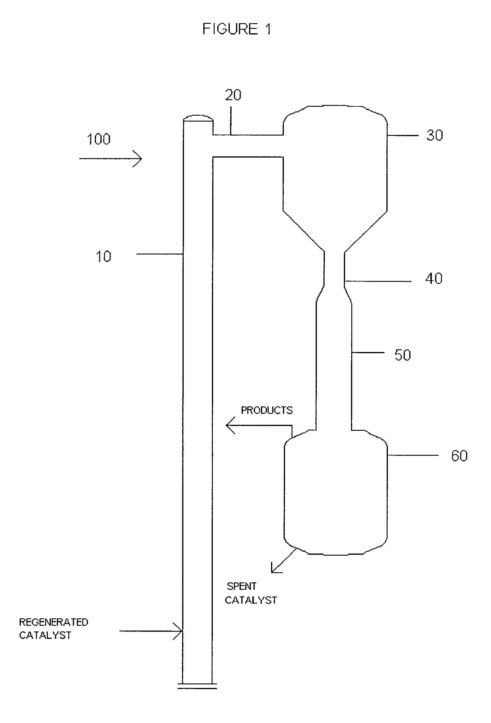
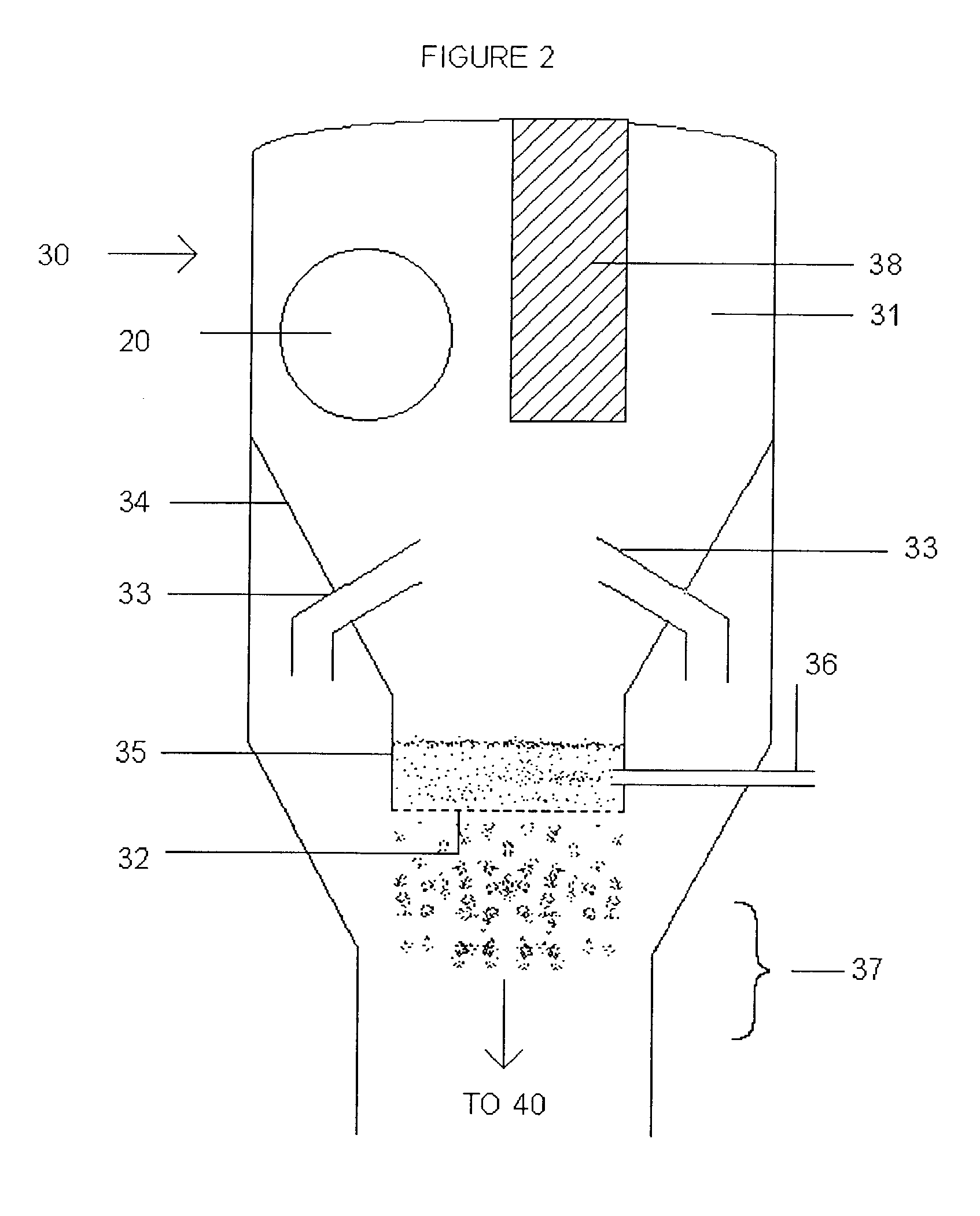
[0150]The cracking reaction was carried out in an apparatus according to the invention, under overall reaction conditions as stated above.

[0151]Yields of both the Riser Technology column and the invention column are obtained from pilot units, the comparison being established under iso-coke conditions.

[0152]Reaction yields are as listed in Table 2 below.

[0153]

TABLE 2RISERYIELDS BASED ONTECHNOLOGYINVENTIONFEEDWeight %Weight%Fuel gas3.63.5LPG (incl. propylene)20.321.0Gasoline, C5-220° C.47.552.6LCO12.19.6Decanted Oil8.04.8Coke8.58.5Tot...


PUM

PropertyMeasurementUnit
anglesaaaaaaaaaa
anglesaaaaaaaaaa
velocityaaaaaaaaaa

Abstract

An apparatus for downflow fluid catalytic cracking is described, which comprises a regenerated catalyst riser carrying regenerated catalyst and a carrying fluid, those being directed through a crossover section to a distributor that will centrifuge gas and separate catalyst from carrying fluid, the catalyst being directed to a downflow reactor through a distributing basket provided with perforations. The upper part of the reactor is provided with feed injectors, which atomize the feed so that feed vaporization and feed and catalyst admixture is optimized. After the cracking reaction in downflow reactor, reaction products are separated and spent catalyst is directed to stripping and regeneration sections. The FCC process carried out in the apparatus is also described.

Description

FIELD OF THE INVENTION[0001]The present invention relates to an apparatus and to a process for downflow fluid catalytic cracking, the apparatus comprising a regenerated catalyst riser, a distributor for said regenerated catalyst, a downflow reactor, and a quick separation device inside a collector vessel. More specifically, the invention relates to an apparatus and to a process for downflow catalytic cracking of heavy feeds with maximization of catalytic cracking and valuable products which makes use of a regenerated catalyst distributor the design of which allows a more evenly distribution of the catalyst to be contacted with the feed in the downflow reactor reaction zone. Besides the said distributor, the apparatus as a whole incorporates other favorable features, which add to the performance of the whole system and ultimately to the downflow FCC process.BACKGROUND INFORMATION[0002]FCC processes are well known. In the more usual FCC processes employing riser reactors the catalyst ...

Claims


Application Information

Patent Timeline
Patent Type & Authority Patents(United States)
IPC IPC(8): C10G11/00B01J8/18B01J8/00C10G11/18
CPCB01J8/003B01J8/0055C10G11/18B01J8/1881B01J8/1818
Inventor PINHO, ANDREA DE REZENDERAMOS, JOSE GERALDO FURTADOHUZIWARA, WILSON KENZODOS SANTOS, CLAUDIO FONSECA MACHADOSILVA, MAURODUBOIS, AURELIO MEDINAJUNIOR, NELSON PATRICIOMEDEIROS, JORIVALDOFREIRE, PAULO SERGIONUNES, WALCONDINEY PEREIRAASSUMPCAO, PAULO SERGIO MOREIRA
Owner PETROLEO BRASILEIRO SA (PETROBRAS)
Why Eureka
Try Eureka