Air actuated pneumatic impact wrench lug bolt tool

a pneumatic impact wrench and air-actuated technology, which is applied in the direction of wrenches, power-driven tools, screwdrivers, etc., can solve the problems of man-powered products and difficulty in operating wrenches with these extensions in limited areas, and achieve the effect of reducing the number of parts and reducing the cost of production

Inactive Publication Date: 2006-08-15
H B PROD
View PDF18 Cites 19 Cited by
  • Summary
  • Abstract
  • Description
  • Claims
  • Application Information

AI Technical Summary

Benefits of technology

[0007]These and other problems and disadvantages associated with the prior art are overcome by one form of the invention disclosed herein by providing, a durable and reliable device utilizing compressed air to enable a user to loosen or tighten fasteners that are located in areas that would otherwise be difficult to access.

Problems solved by technology

However, this product is still nonetheless man powered as it is still necessary for a person to provide the actual “force” required to use the wrench (apply the torque).
Furthermore, as a consequence of a longer handle, it would also be difficult to operate wrenches with these extensions in limited areas.

Method used


Image

  • Air actuated pneumatic impact wrench lug bolt tool
  • Air actuated pneumatic impact wrench lug bolt tool
  • Air actuated pneumatic impact wrench lug bolt tool

Examples


Embodiment Construction

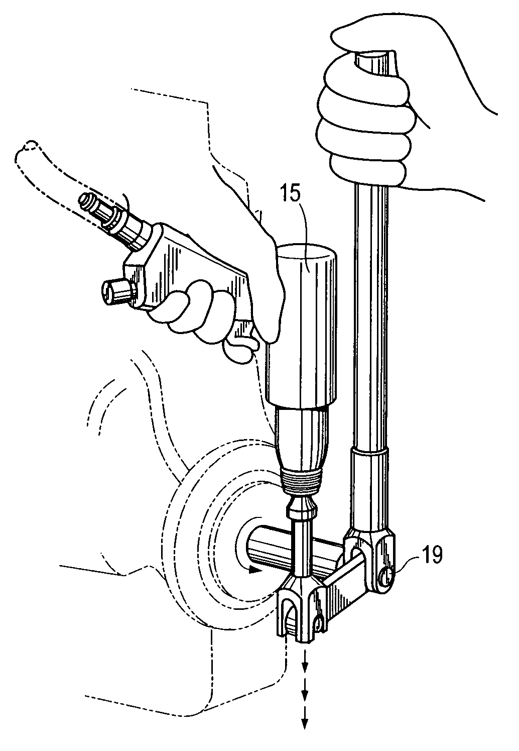
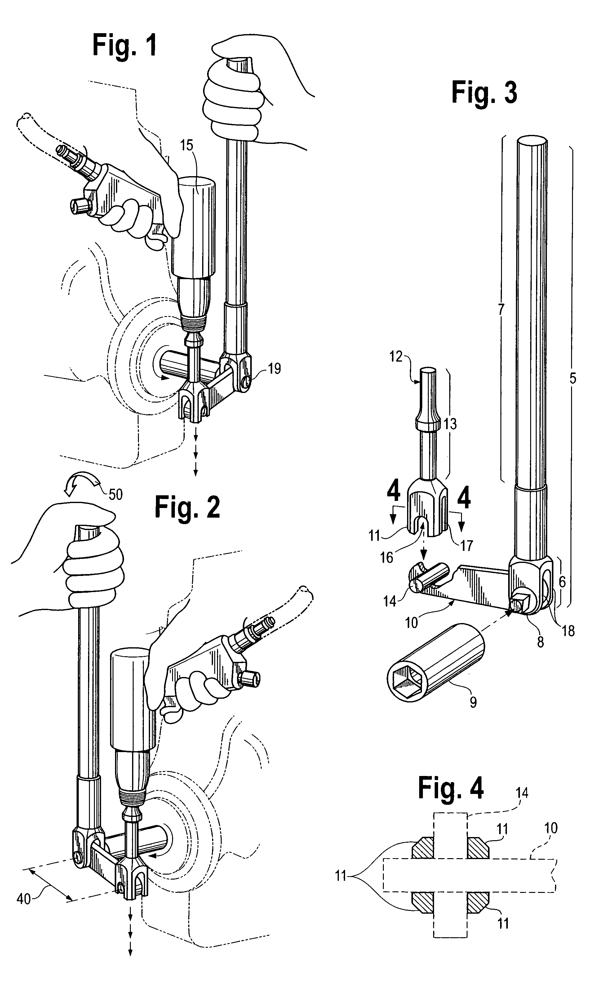
[0018]Referring to FIG. 1, the present invention is combined with a pneumatic hammer 15 that supplies a downward force to the device. The pneumatic hammer 15 is connected to any source providing air pressure, typically in a garage or from a compressor. The pneumatic hammer 15 is removeably attached to the transfer fixture 13 via a standard pneumatic hammer shank 12 creating a snug fit. This fit enables the pneumatic hammer 15 to apply a downward force using air pressure that is transferred to the device via the transfer fixture 13 and eventually to the socket 9 enabling a user to loosen or tighten fasteners.

[0019]As seen in FIGS. 3 and 4, the transfer fixture 13 is removeably associated with the lever 10. This association is enabled by the fit between the four pronged head 11 of the transfer fixture 13 and the solid cylinder 14 fixedly attached to the lever 10. The four pronged head 11 has a cutout on each face, the opposite faces' cutouts mirroring the shape of one another. One pai...


PUM


Abstract

The invention relates to a device utilizing compressed air for loosening and tightening fasteners that are located in hard to access areas. The device enables a single operator to stabilize the device while applying pressure via a pneumatic hammer to loosen or tighten fasteners. The device uses socket principles that enable the user to switch the sockets and provide a wide variety of options to accommodate the shapes and sizes of the fasteners.

Description

BACKGROUND OF THE INVENTION[0001]The variety in the available types of ratchets and wrenches has increased over the years. The need for advancement in the development of quality engineered wrenches and ratchets and a corresponding need to maneuver these tools in small places has long been desired. Ratchet wrenches which are hand held and driven by a motor are known in the art. The present invention is not limited by a drive motor and thus is a more reliable and durable tool. Examples of prior art devices with drive motors are illustrated in U.S. Pat. Nos. 4,346,630 and 4,993,288.[0002]U.S. Pat. No. 4,346,630, issued to Hanson is considered a pneumatic or power wrench. This patent embodies a ratchet wrench having a drive motor and a member which drives a shaft configured to carry a socket to fit to a nut to be turned. To provide the necessary torque to turn a nut, this patent utilizes a drive motor which is preferably an air motor.[0003]U.S. Pat. No. 4,993,288 issued to Anderson et a...

Claims


Application Information

Patent Timeline
Patent Type & Authority Patents(United States)
IPC IPC(8): B25B19/00B25B21/00B25B23/14B25B21/02
CPCB25B21/02B25B19/00
Inventor HAMANN, JAMES E.HAMANN, GEORGE R.
Owner H B PROD
Why Eureka
Try Eureka