
Container and sealing cover

Inactive Publication Date: 2006-08-15
SNAPWARE CORP
View PDF8 Cites 92 Cited by
  • Summary
  • Abstract
  • Description
  • Claims
  • Application Information

AI Technical Summary

Benefits of technology

[0008]A pair of latch handles are pivotally mounted on opposite sides of the cover along the outer rim flange thereof with each latch handle being provided with a protruding locking tab arranged to snap under a section of the peripheral upper edge of the container wall when the latch handle is rotated downwardly to lock the cover in a sealing relationship over the container mouth. The outer rim skirt of the cover does not extend under the peripheral upper edge of the cover so that the cover can be readily removed when the latch handles are rotated upwardly to disengage the locking tabs from the peripheral upper edge of the container. Also when one of the latch handles is rotated to its unlocked position expanded fluid within the container will cause the lid (or a portion thereof) to rise slightly during microwave cooking to provide the necessary venting action to prevent excess pressure build-up.

Problems solved by technology

Such containers are normally fairly rigid, but may be subject to some amount of flexure especially where the lid or cover is arranged to be peeled off of the container mouth.
Such sealing arrangements generally require considerable effort to force the lid onto the sealing bead during the closing procedure and perhaps greater effort to peal the lid away from the container during the opening process.
While some lids are provided with one or more outwardly extending tabs to accommodate a user's fingers, the opening procedure may be quite difficult for a person suffering from arthritis or tendinitis.
In addition, the lids of such sealable containers often become distorted through heating, dishwashing or refrigeration procedures making lid replacement difficult or impossible.
In either case the separate sealing member, i.e., O-ring or gasket involves not only added manufacturing costs, but is subject to being misplaced or lost during use of the container.

Method used


Image

  • Container and sealing cover
  • Container and sealing cover
  • Container and sealing cover

Examples


Embodiment Construction

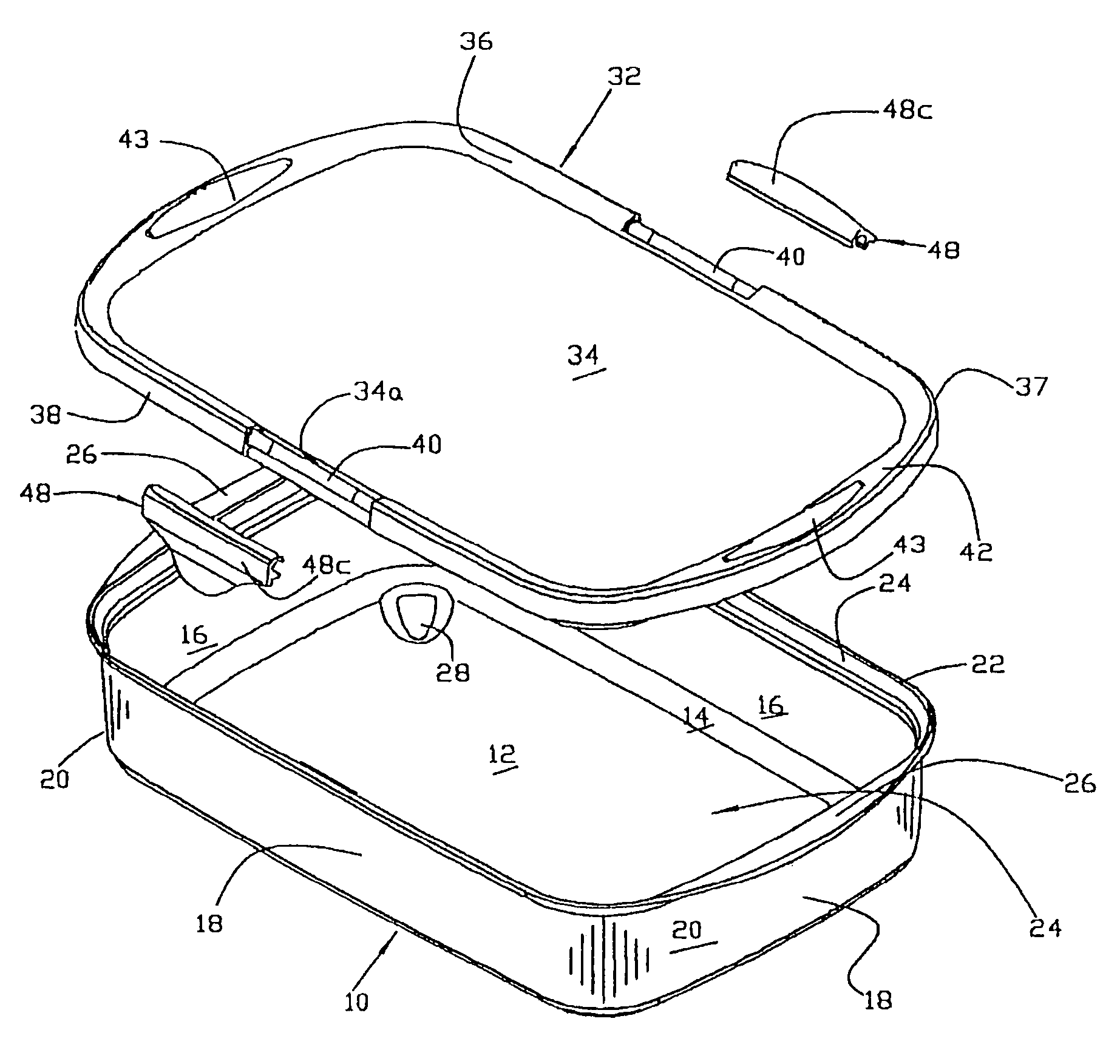
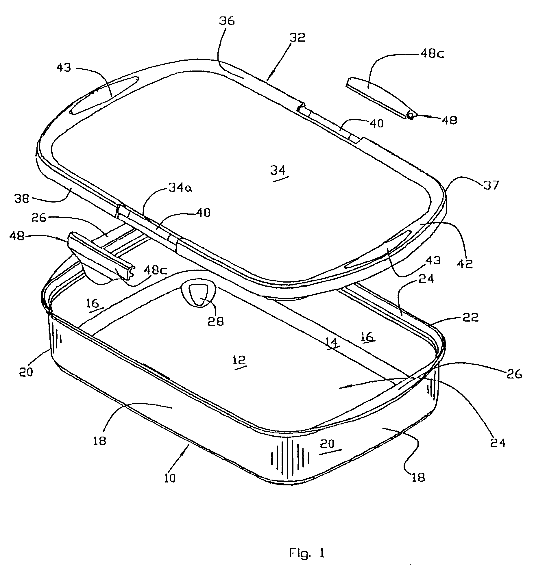
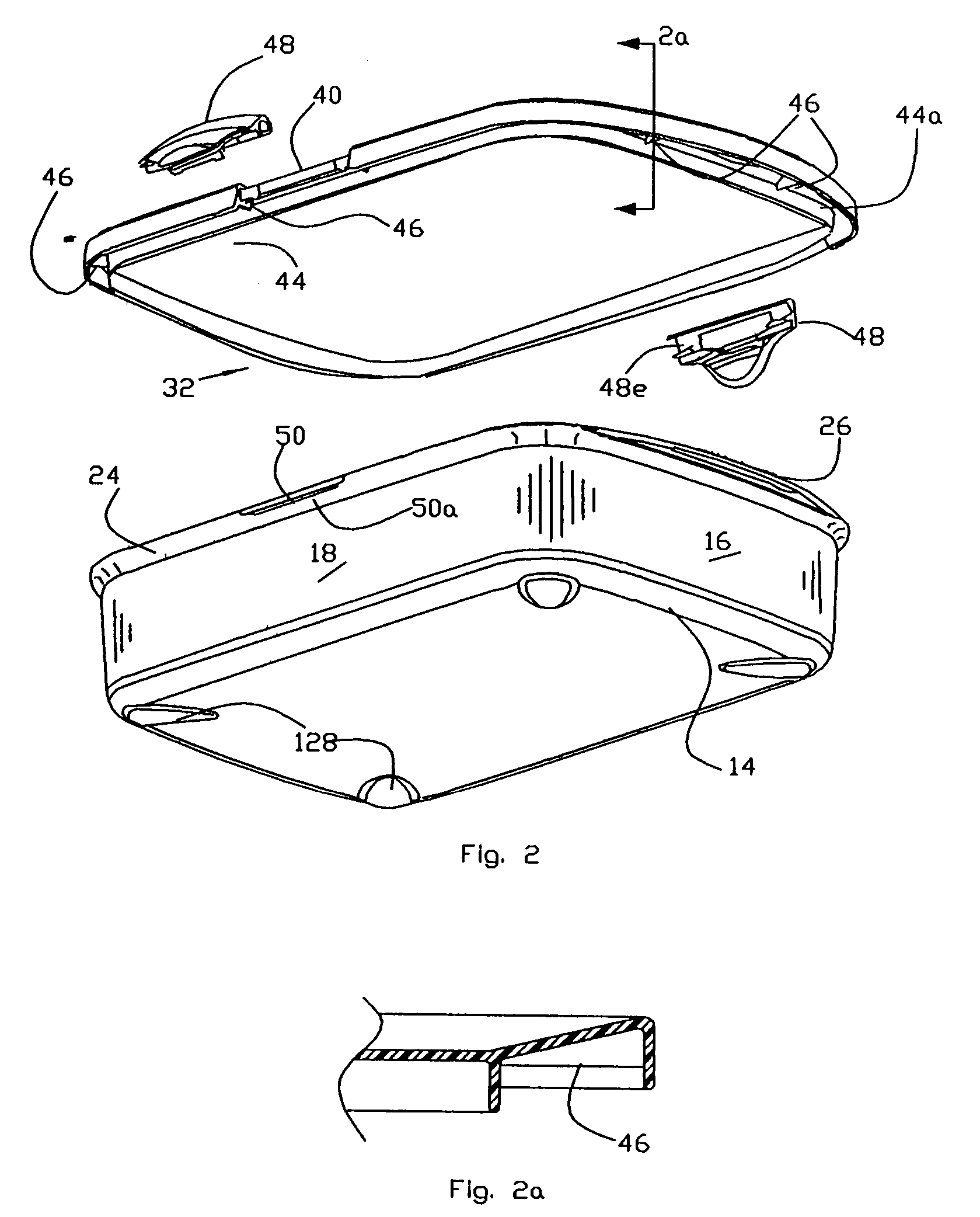
[0044]Referring now to FIGS. 1–4, the container 10 of the present invention includes a flat bottom wall 12 which merges at its periphery, via a rounded corner 14, with a peripheral wall, comprising end walls 16 and side walls 18. As discussed previously, while the container shown in the drawings has a rectangular shape, the container of the present invention may have a circular or oval shape with only a peripheral upstanding wall. The end and side walls of the container 10 are merged, via rounded corners 20, as shown. The peripheral wall (16, 18) terminates in an upper edge 22, via an outwardly extending convex shaped segment 24. The edge 22 surrounds and defines an open top or mouth 25 of the container 10 and forms a pair of horizontally protruding handles 26 above the end walls 16 as shown. The top surface of the handles are substantially level with the plane of the edge 22 simplifying the manufacturing process and allowing the cover to overlie the handles as illustrated for examp...


PUM

PropertyMeasurementUnit
Angleaaaaaaaaaa
Angleaaaaaaaaaa
Angleaaaaaaaaaa

Abstract

A container and sealable cover in which the container has a bottom wall and an upstanding peripheral wall terminating in an upper edge surrounding an open mouth. The peripheral wall is inclined outwardly at a slight angle to the vertical or alternatively vertically disposed. A replaceable cover is provided with a central top planar wall and an inverted U-shaped periphery terminating in an outer rim skirt. A contiguous downwardly extending sealing fin is disposed inwardly of the skirt for forming an interference fit with the inside surface of the upper portion of the container peripheral wall when the cover is installed over the container mouth. The fin may be substantially vertically disposed or canted outwardly at a small angle to the vertical depending upon the inclination of the peripheral wall. A pair of latches are rotatably mounted on the cover adjacent the outer rim skirt and arranged to engage protruding latch hooks on the container peripheral wall to releasably secure the cover over the container mouth.

Description

RELATED APPLICATION[0001]This application is a continuation of application Ser. No. 10 / 204,684 filed Aug. 23, 2002 now abandoned entitled CONTAINER AND SEALING COVER which is a 371 of PCT / US01 / 41317 filed Jul. 10, 2001 claims priority to and PCT / US01 / 02434, filed Jan. 25, 2001, entitled CONTAINER AND SEALING COVER.FIELD OF THE INVENTION[0002]This invention relates generally to a container for storing foods, liquids and other articles and a replaceable cover or lid capable of providing a tight seal and more particularly to the container cover which is suitable for use in microwave cooking and in automatic dish washers.BACKGROUND ART AND OBJECTS OF THE INVENTION[0003]Food storage containers are generally made of a plastic material such as polypropylene or polyethylene polymers or copolymers. Such containers are normally fairly rigid, but may be subject to some amount of flexure especially where the lid or cover is arranged to be peeled off of the container mouth. Most such container / l...

Claims


Application Information

Patent Timeline
IPC IPC(8): B65D45/16B65D43/02
CPCB65D43/0218B65D45/16B65D2543/0012B65D2543/0087B65D2543/00518B65D2543/00537B65D2543/00555B65D2543/00296
Inventor LOWN, JOHN M.MELVIN, DAVID A.
Owner SNAPWARE CORP
Learn More