
Fuel injector with dual piezo-electric actuator

a piezoelectric actuator and fuel injector technology, which is applied in the direction of fuel injection apparatus, spraying apparatus, feeding system, etc., can solve the problems of high dependence on the injection rate of fuel, difficult to achieve precise fuel injection, and relative slow to respond to any desired pressure change, etc., to achieve the effect of reducing transient emissions

Inactive Publication Date: 2008-01-17
DETROIT DIESEL CORP
View PDF13 Cites 9 Cited by
  • Summary
  • Abstract
  • Description
  • Claims
  • Application Information

AI Technical Summary

Benefits of technology

[0011]In one embodiment, the restrictive passage leading to the chamber is more restrictive than the third passage. This restriction prevents pressure build up in the chamber when the second control valve is open, i.e., any pressure leading through the restriction is immediately relieved by the chamber and third passage opening to the low pressure return. In one embodiment, the piezo-electric stacks are controlled by a variable voltage source.
[0014]In this fashion, a fuel injection device for an internal combustion engine such as a Diesel engine can with precision, control pressure and initial fuel injection rates and can provide for pilot injection, main injection and post injection by using two piezo-electric actuators for each injector. Such precise control of injection rates provides better control between sequential cycles and reduced transient emissions.

Problems solved by technology

Precise fuel injection is often difficult to achieve because many fuel injectors' performance is dependent on the speed and load of the engine.
Secondly, many fuel injection devices rely on the pressure within a common rail which has a relatively large volume and provides a relatively constant pressure.
A common rail, due to its relatively large volume, is relative slow to respond to any desired changes of pressure for sequential cycles of the fuel injector.
However, the valve's injection rate of delivery is highly dependent on the engine speed.
Attempts have been made to contour the injection rates by using injector cams with high velocity profiles but these specialized cams may provide only limited effect due to mechanical design constraints.

Method used


Image

  • Fuel injector with dual piezo-electric actuator
  • Fuel injector with dual piezo-electric actuator
  • Fuel injector with dual piezo-electric actuator

Examples


Embodiment Construction

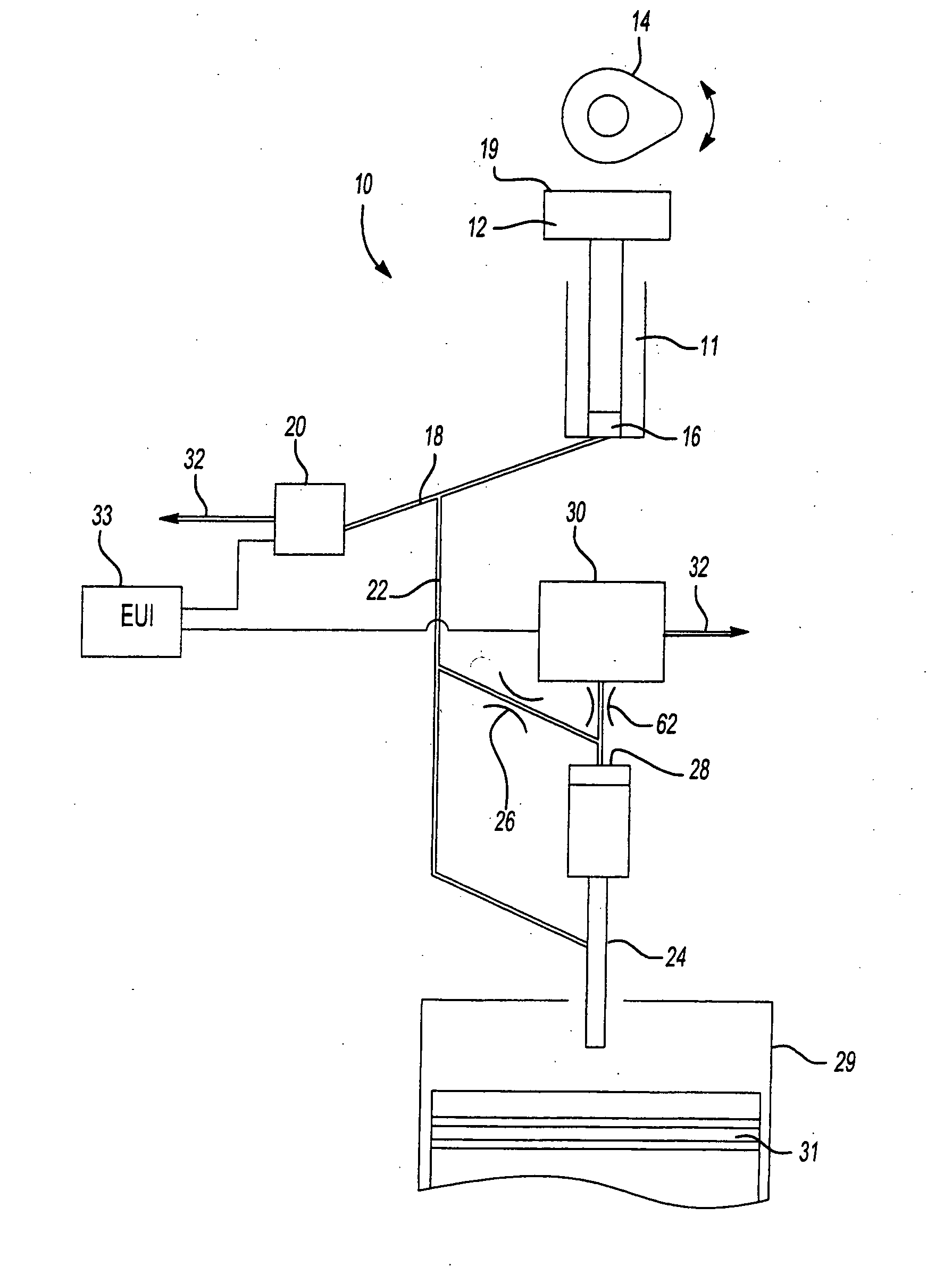
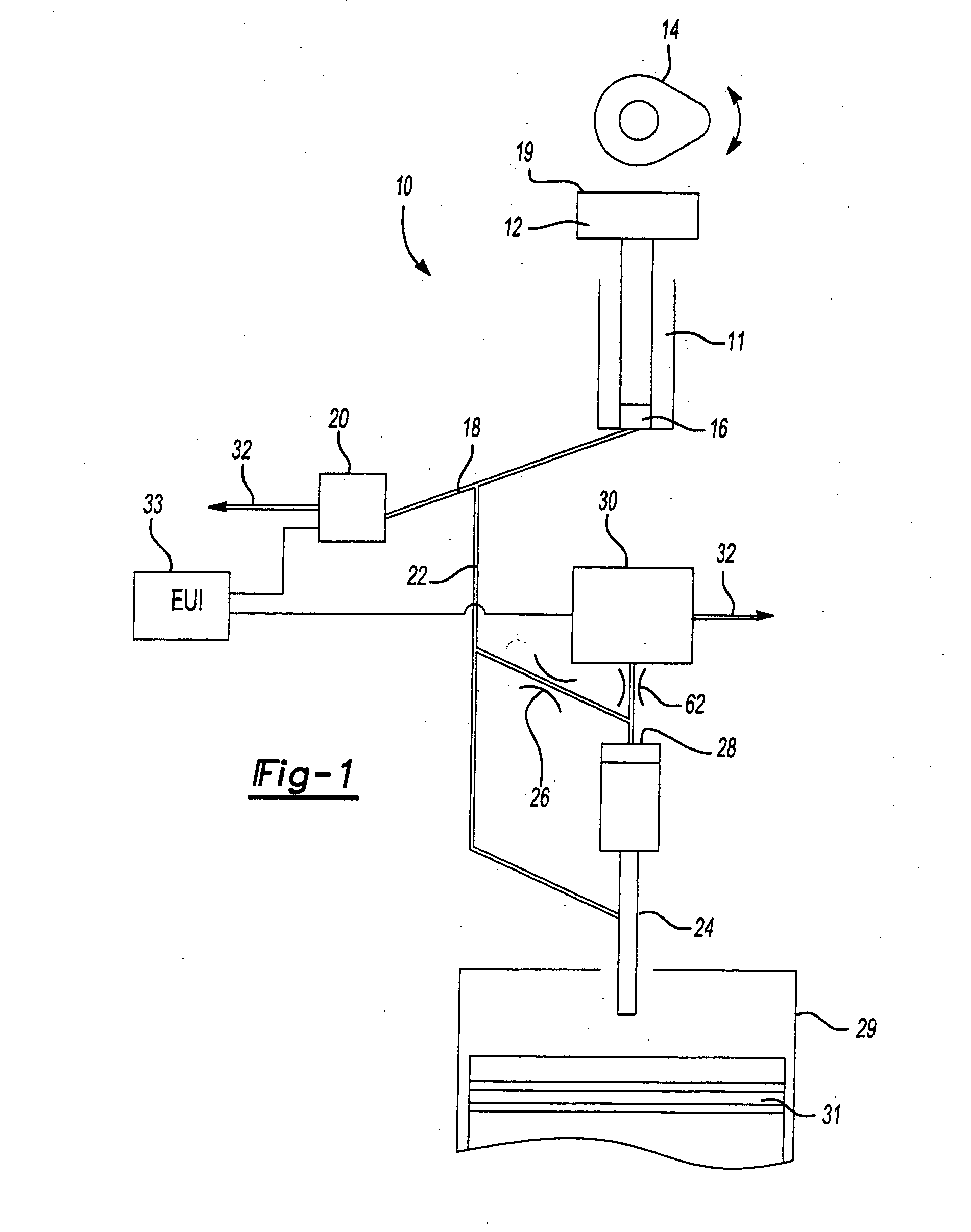
[0025]Referring now to FIG. 1, a hydraulic schematic shows an injector device 10 having a main body 11 with a sliding plunger 12 operated by a cam or rocker arm 14 of an internal combustion engine such as of a diesel engine. The plunger causes a displacement of fluid in cavity 16 and conduit 18 leading to a control actuator 20 and a second passage 22 which leads to a nozzle valve 24 which is operably mounted to a combustion chamber 29 that receives piston 31 in the Diesel engine. A restrictive passage 26 in communication with passage 22 leads to a chamber 28 on the back side of nozzle valve 24. A second control actuator 30 is in communication with chamber 28.

[0026]The first control actuator 20 selectively opens or closes communication of passages 18 and 22 to a low pressure spill way 32. Similarly, second control valve 30 selectively communicates chamber 28 to low pressure spill way 32. Each control valve 20 and 30 is operably connected to an electronic control unit (EUI) 33 capable...


PUM


Abstract

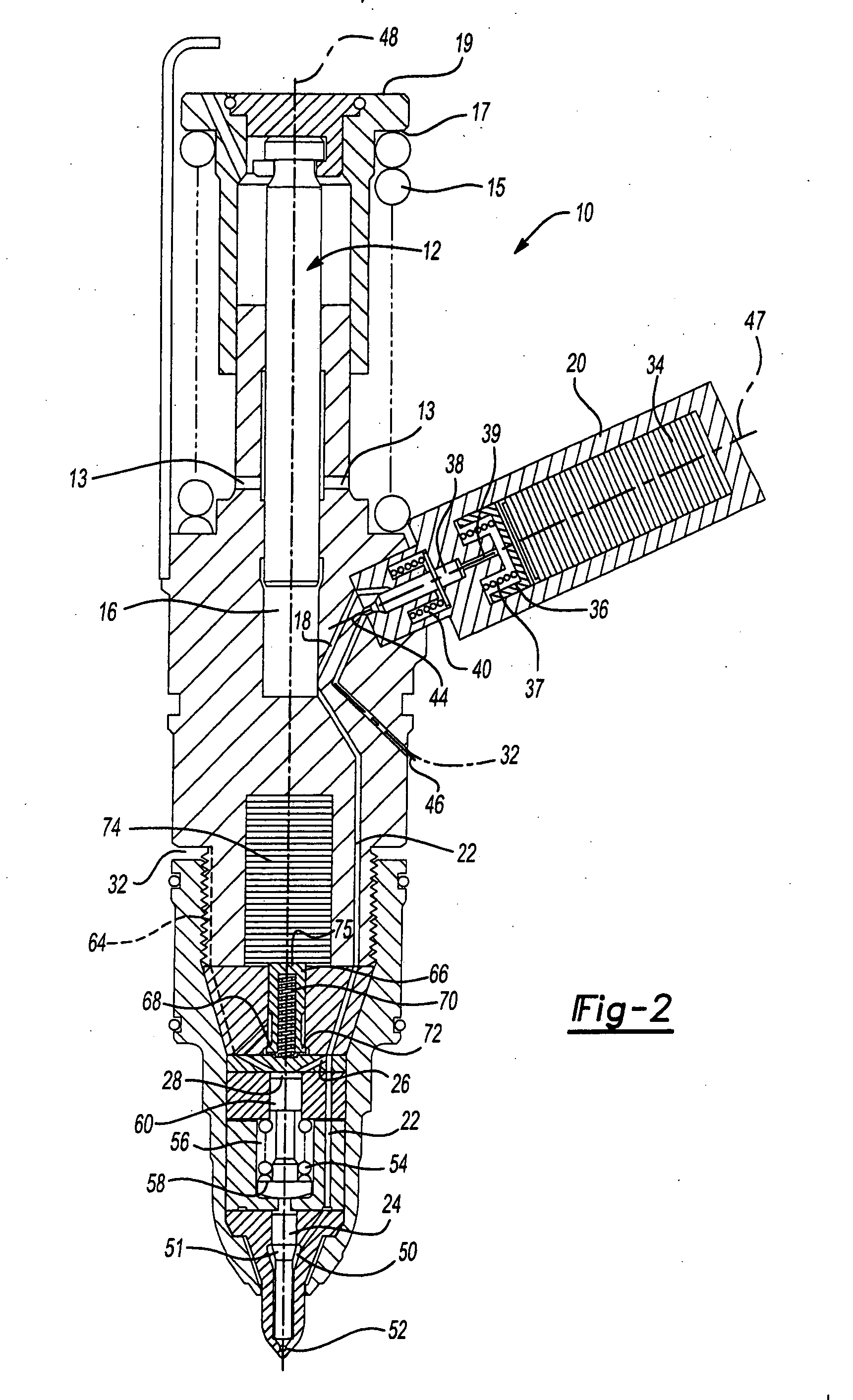
A fuel injector 10 for a Diesel engine has a plunger 12 and two control valves 20 and 30 for controlling the injection of fuel from the main supply cavity to the discharge port 52. Each control valve 20 and 30 are actuated through piezo-electric stacks 34 and 74 connected to a electronic variable voltage supply 33.

Description

TECHNICAL FIELD[0001]The field of this invention relates generally to a fuel injector assembly for an internal combustion engine and more particularly to a fuel injector having dual piezo-electric actuators.BACKGROUND OF THE DISCLOSURE[0002]Fuel injector assemblies are often utilized in internal combustion engines for delivering a metered measure of fuel to the combustion chamber. The injected fuel mixes with air within the chamber for combustion. Precise metering and timing of the fuel injection provides for better combustion, thus better horsepower, fuel economy and performance. In addition precise control of the fuel injection has also been known to improve emission performance.[0003]Piezo-electric material provides for a rapid response when a voltage is applied to the material. When piezo-electric material is incorporated in a control actuator of a Diesel fuel injector it is faster and more responsive than solenoid actuated or mechanically actuated valves. Furthermore, the rate ...

Claims


Application Information

Patent Timeline
IPC IPC(8): F02M57/02F02M59/46
CPCF02M47/027F02M63/0026F02M57/023
Inventor GONEY, KAYHAN HALILJIANG, HEKALISH, YURY
Owner DETROIT DIESEL CORP
Learn More