Control of induction system hydrocarbon emissions

a technology of induction system and hydrocarbon emission control, which is applied in the direction of machine/engine, fuel injection apparatus, feed system, etc., to achieve the effect of reducing or preventing hydrocarbon emissions and preventing fuel pressure increas

Active Publication Date: 2007-06-05
GM GLOBAL TECH OPERATIONS LLC
View PDF6 Cites 8 Cited by
  • Summary
  • Abstract
  • Description
  • Claims
  • Application Information

AI Technical Summary

Benefits of technology

[0004]In an embodiment of the invention, a method for reducing or preventing hydrocarbon emissions from an air induction system after an engine is shut down by preventing increase in fuel pressure in the fuel rail during diurnal temperature increases. Fuel pressure in the fuel rail may cause fuel injector leakage, which is avoided when there is no pressure in the fuel line and fuel rail.
[0006]In an embodiment of the invention, an automotive vehicle having a fuel tank containing fuel and a fuel pump that supplies fuel under pressure through a fuel line to engine fuel injectors extending into an air intake manifold of an air induction system, includes in the fuel pump a valve that, when the engine is not operating, opens after the fuel has cooled to reduce fuel pressure in the fuel line to ambient fuel tank pressure and remains open until next engine start. The pressure release valve prevents further pressure build up in the fuel line due to diurnal temperature increase that may cause fuel to leak from the fuel injectors into the air induction system and be emitted into the atmosphere.

Problems solved by technology

After engine shut down, the fuel in the rail is left under pressure to avoid fuel boiling, which can cause problems when the engine is re-started.

Method used


Image

  • Control of induction system hydrocarbon emissions
  • Control of induction system hydrocarbon emissions
  • Control of induction system hydrocarbon emissions

Examples


Embodiment Construction

[0011]The following description of the preferred embodiment(s) is merely exemplary in nature and is in no way intended to limit the invention, its application, or uses.

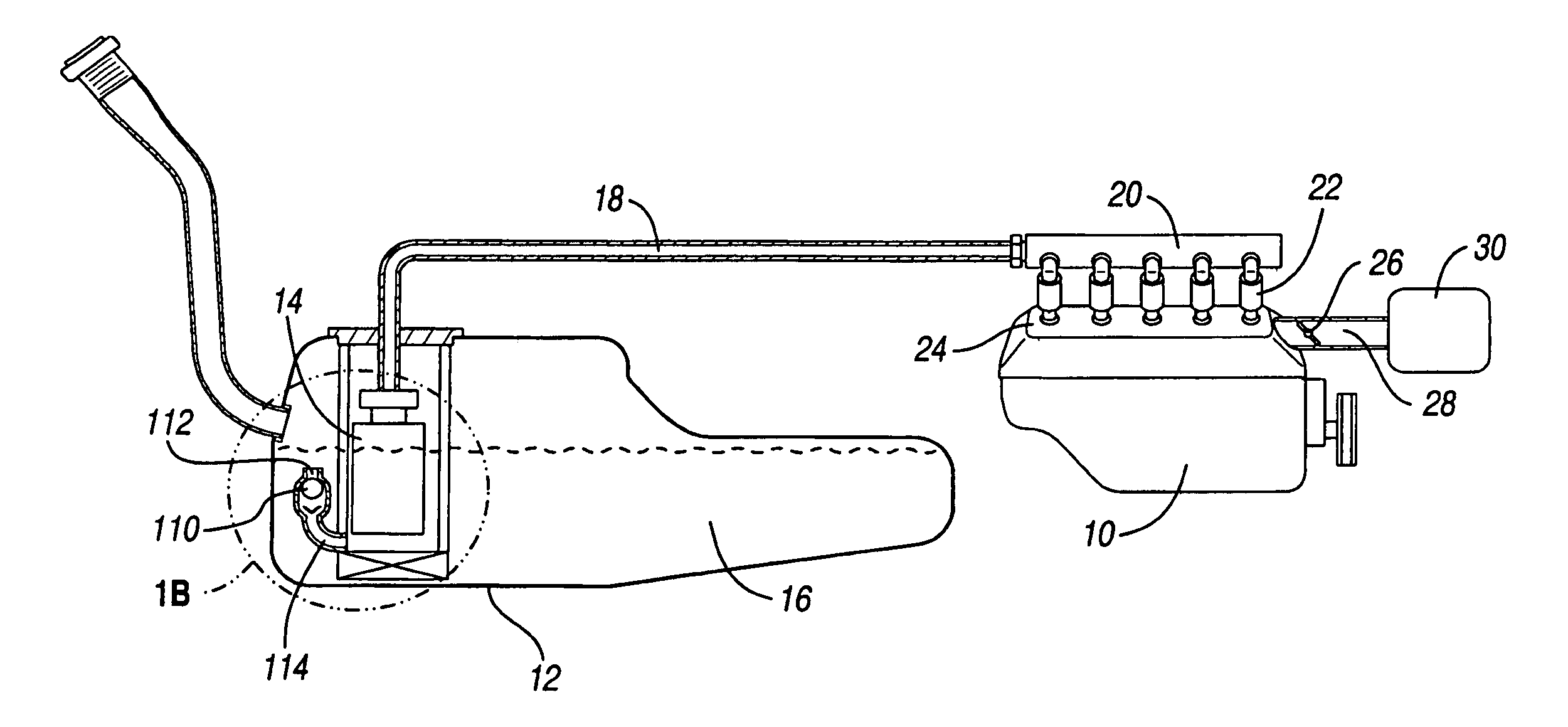
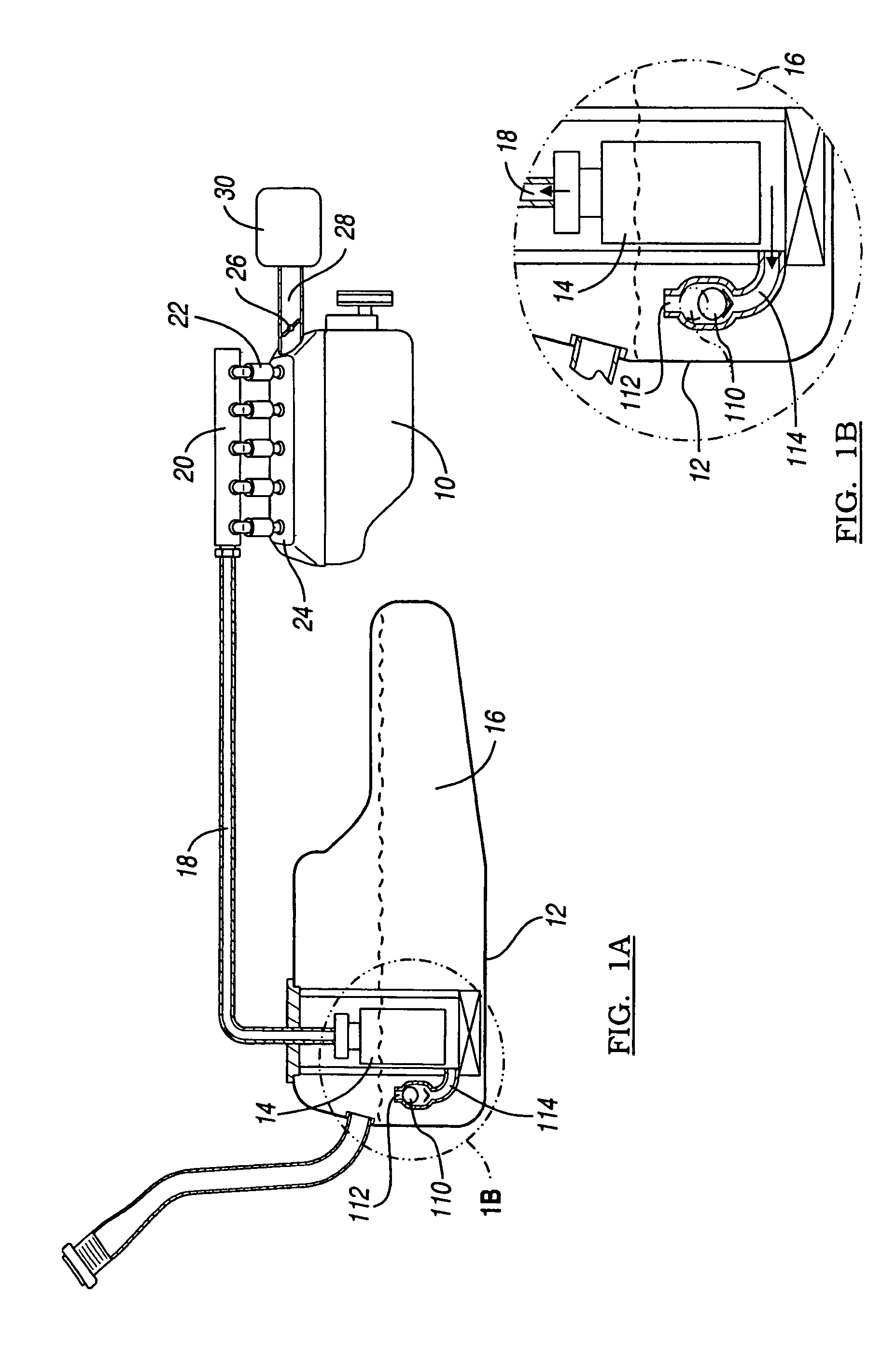
[0012]Referring now to FIG. 1, an internal combustion engine 10 having an intake manifold 24 and fuel tank 12 is illustrated. The engine may be part of a conventional (non-hybrid) vehicle including only the internal combustion engine or part of a hybrid vehicle including the internal combustion engine and an electric motor (not shown). The engine 10 typically burns gasoline, ethanol, and other volatile hydrocarbon-based fuels. During engine operation, fuel 16 is delivered from the fuel tank 12 by a fuel pump 14 through fuel line 18 to a fuel rail 20. Fuel injectors 22 located along fuel rail 20 inject fuel into air intake manifold 24, from where the air / fuel mixture is drawn into cylinders of the engine 10 and combusted to provide power to the engine 10. Air intake into intake manifold 24 is controlled by a valve 26 i...


PUM


Abstract

A method and apparatus for reducing or preventing hydrocarbon emissions from an air induction system of an automotive vehicle during diurnal periods opens the fuel line to ambient fuel tank pressure when fuel pressure in the fuel line decreases due to cooling of the fuel.

Description

FIELD OF THE INVENTION[0001]The present invention relates generally to systems and methods for controlling hydrocarbon emissions in automotive vehicles.BACKGROUND OF THE INVENTION[0002]The automotive industry has actively sought improved emissions reduction, including reduction in emissions due to gasoline evaporation. Gasoline includes a mixture of hydrocarbons ranging from higher volatility butanes (C4) to lower volatility C8 to C10 hydrocarbons. When vapor pressure increases in the fuel tank due to conditions such as higher ambient temperature or displacement of vapor during filling of the tank, fuel vapor may flow through openings in the fuel tank and escape into the atmosphere. To prevent fuel vapor loss into the atmosphere, the fuel tank is vented into a canister called an “evap canister” that contains an adsorbent material such as activated carbon granules. As the fuel vapor enters an inlet of the canister, the fuel vapor diffuses into the carbon granules and is temporarily a...

Claims


Application Information

Patent Timeline
Patent Type & Authority Patents(United States)
IPC IPC(8): F02M37/04
CPCF02M37/20F02M37/00F02M37/04F02M69/00
Inventor REDDY, SAM R.COLEMAN, DAVID H.
Owner GM GLOBAL TECH OPERATIONS LLC
Why Eureka
Try Eureka