Fuel injection valve for internal combustion engines

a technology for internal combustion engines and fuel injection valves, which is applied in the direction of fuel injection apparatus, machines/engines, feed systems, etc., can solve the problems of shortening the service life of the fuel injection valve, bulging out of the valve body, and increasing wear and tear

Inactive Publication Date: 2004-03-18
ROBERT BOSCH GMBH
View PDF7 Cites 10 Cited by
  • Summary
  • Abstract
  • Description
  • Claims
  • Application Information

AI Technical Summary

Problems solved by technology

The known fuel injection valve has the disadvantage, however, that because of the fuel, which is introduced into the valve body at very high pressure, deformation of the pressure chamber and hence bulging out of the valve body occurs.
This can lead to increased wear and hence

Method used


Image

  • Fuel injection valve for internal combustion engines
  • Fuel injection valve for internal combustion engines
  • Fuel injection valve for internal combustion engines

Examples


Embodiment Construction

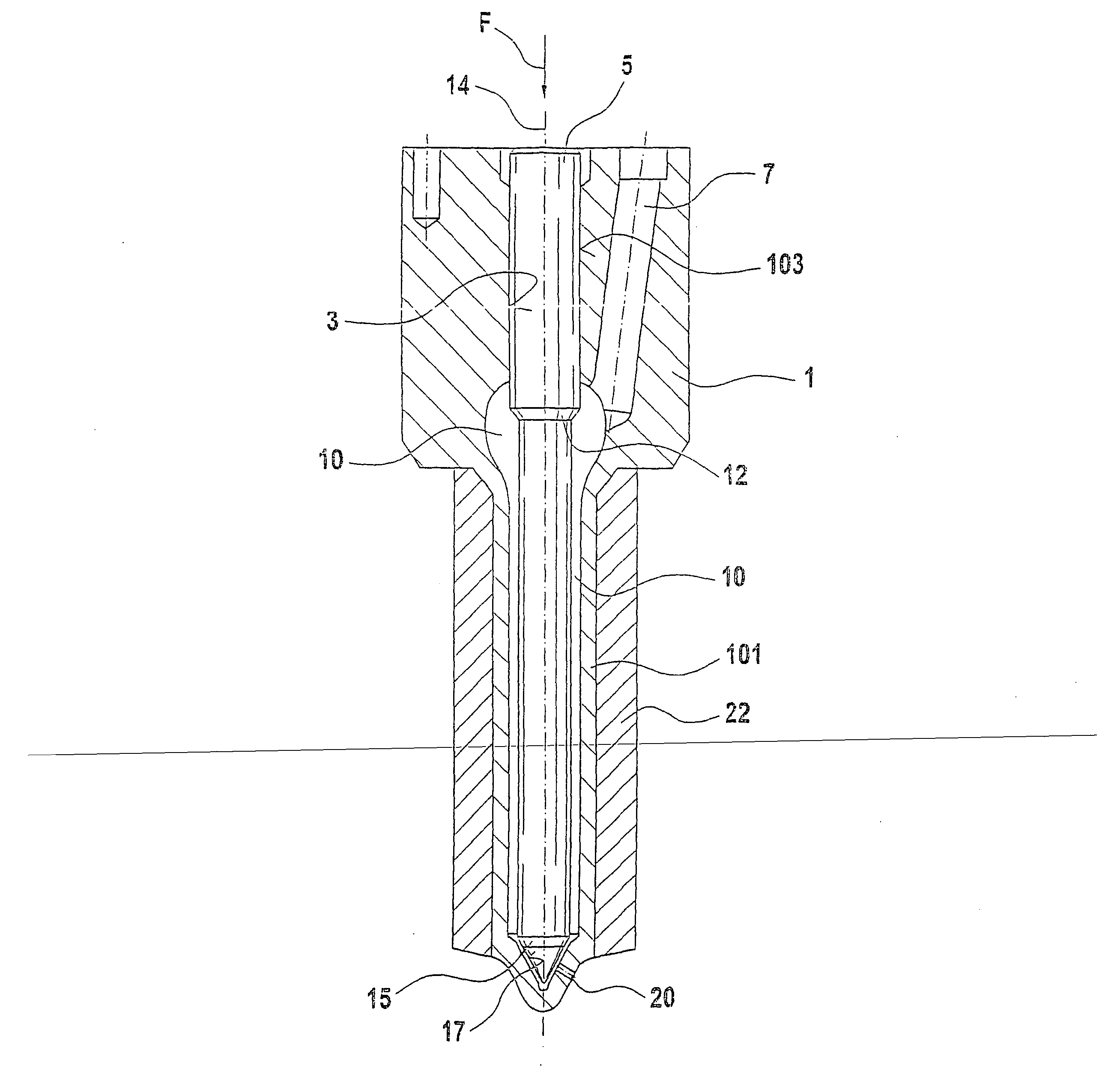
[0015] In FIG. 1, a longitudinal section is shown through a fuel injection valve of the invention, in its essential region. The fuel injection valve has a valve body 1 with a bore 3, which on its end toward the combustion chamber changes over into a substantially conical valve seat 17. In the end region toward the combustion chamber of the valve body 1, at least one injection opening 20 is embodied, which connects the valve seat 17 with the combustion chamber of the engine. In the bore 3, a valve member 5 is disposed longitudinally displaceably; the valve member 5 is embodied in pistonlike form and is guided in a guide portion 103 of bore 3 on the end remote from the combustion chamber. The valve member 5 narrows from the guide portion 103 toward the combustion chamber, forming a pressure shoulder 12, and on its end toward the combustion chamber, it changes over into a substantially conical valve sealing face 15, which cooperates with the valve seat 17. By means of a radial enlargem...


PUM


Abstract

A fuel injection valve for internal combustion engines, having a valve body (1) in which a bore (3) is embodied that has a longitudinal axis (14), and on the end toward the combustion chamber of which bore a valve seat (17) is embodied. In the region of the valve seat (17), at least one injection opening (20) is disposed that connects the bore (3) with the combustion chamber of the engine. A valve member (5) is disposed longitudinally displaceably in the bore (3) and with a sealing face (15) cooperates with the valve seat (17) for controlling the at least one injection opening (20). Between the wall of the bore (3) and the valve member (5), a pressure chamber (10) is embodied that can be filled with fuel at high pressure. The valve body (1) is surrounded, in the region of the pressure chamber (10), by a sleeve (22) that has anisotropic strength properties, so that the valve body (1) exhibits less deformation from the pressure in the pressure chamber (FIG. 1).

Description

PRIOR ART[0001] The invention is based on a fuel injection valve for internal combustion engines as generically defined by the preamble to claim 1. One such fuel injection valve is known from German Patent Disclosure DE 196 18 650 A1, for instance. Such a fuel injection valve has a valve body, in which a bore with a longitudinal axis is embodied, and a valve seat is embodied on the end of the bore toward the combustion chamber. In the region of the valve seat there is at least one injection opening in the valve body that connects the bore with the combustion chamber of the engine. In the bore, a valve member is disposed longitudinally displaceably, being guided in a portion of the bore remote from the combustion chamber. On the end toward the combustion chamber, the valve member changes into a sealing face, which cooperates with the valve seat and thus controls the at least one injection opening. Between the valve member and the wall of the bore, a pressure chamber is form that can ...

Claims


Application Information

Patent Timeline
IPC IPC(8): F02M61/10F02M61/14F02M61/16
CPCF02M61/166F02M61/10
Inventor WINTER, JOACHIM
Owner ROBERT BOSCH GMBH
Why Eureka
Try Eureka