Fuel supply system for internal combustion engine with direct fuel injection

a fuel supply system and internal combustion engine technology, applied in the direction of fuel injecting pumps, machines/engines, electric control, etc., can solve the problems of low relatively long start up time, and the fuel supply pump known from the state of the art cannot provide the necessary fuel injection pressure, etc., to achieve high fuel injection peak pressure, low cost, and high pressure

Inactive Publication Date: 2005-10-27
DAIMLER AG
View PDF8 Cites 10 Cited by
  • Summary
  • Abstract
  • Description
  • Claims
  • Application Information

AI Technical Summary

Benefits of technology

[0012] With the system according to the invention, an electrically controllable high pressure pump is not needed in order to provide a high fuel injection peak pressure early on. The pumping volume of the supply pump also called EFP (electrical fuel pump) is so designed that sufficient fuel is supplied to the internal combustion engine at full engine load and high engine speed. Since at startup only a fraction of the pumped fuel volume is needed, the fuel pressure needed during startup can be generated by a normal fuel supply pump and a pressure increase stage which will be called below a hydraulic transmission. After the engine has started, the high pressure pump (HPP) provides for the high pressure needed at engine start-up. It is advantageous in this connection that there is no problem with gas bubbles in the suction line nor with a non-uniform fuel supply to the engine cylinders.
[0013] Furthermore, the whole system can be provided at relatively low costs when compared with conventional systems. With the method according to the invention, which does not require an electrical high pressure fuel pump, a higher energetic overall efficiency can be achieved than with the use of an electric high pressure fuel pump.
[0014] In accordance with the invention, the connecting line between the outlet of the fuel supply pump and the hydraulic transmission is provided upstream of the branch-off line with a first control valve. The hydraulic transmission is arranged between the fuel supply pump and the plurality of injectors or injection nozzles in parallel with the high pressure fuel pump and is capable of generating the high fuel pressure required for the injection during start-up of the internal combustion engine. By the method according to the invention, for the start-up of internal combustion engines with direct fuel injection, the high fuel pressure required can be generated or maintained in the standstill or start up phase of the engine. This advantageously results in a reduction of the startup time required for the engine. The invention therefore provides for an extremely advantageous rapid or instant start of the internal combustion engine.

Problems solved by technology

The fuel supply pumps known from the state of the art cannot provide the necessary fuel injection pressure.
Before reaching the above minimum fuel pressure, engines with direct fuel injection cannot start properly.
This results in relatively long start up times and detrimentally affects particularly start / stop operation of the engine.
However, with this arrangement, the formation of gas bubbles in the suction line of the hydraulic fuel pump (HDP) cannot safely be avoided.
Also, the use of an electric fuel supply or high pressure pump has the disadvantage that these pumps are very expensive and subject to failure, that, in order to provide the necessary fuel pressure, they must be relatively large and that such pumps generate certain noises.

Method used


Image

  • Fuel supply system for internal combustion engine with direct fuel injection
  • Fuel supply system for internal combustion engine with direct fuel injection
  • Fuel supply system for internal combustion engine with direct fuel injection

Examples


Embodiment Construction

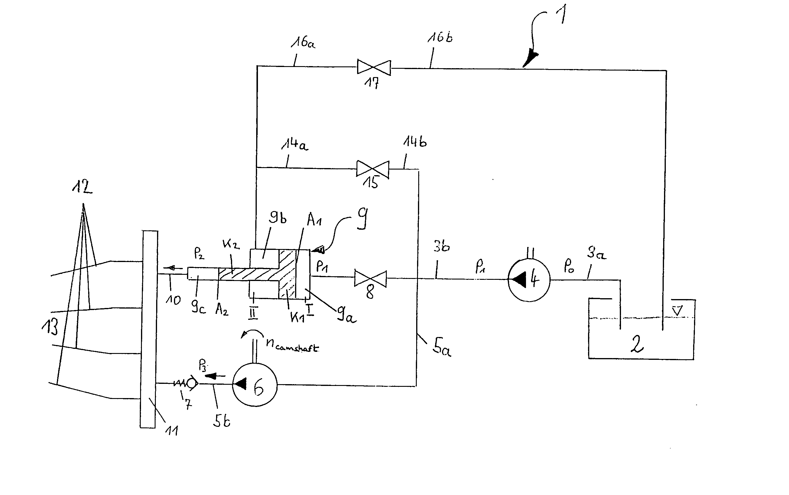
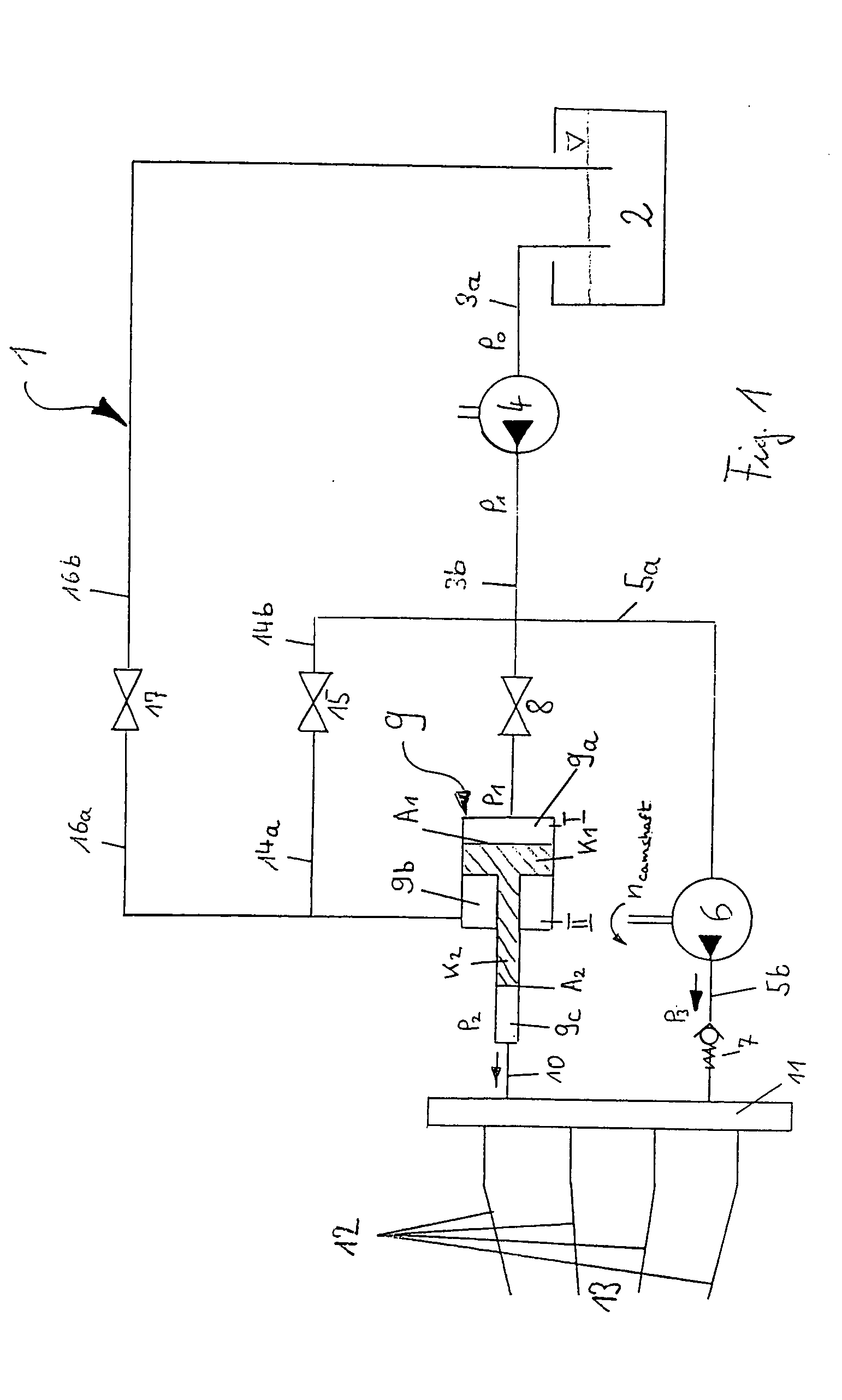
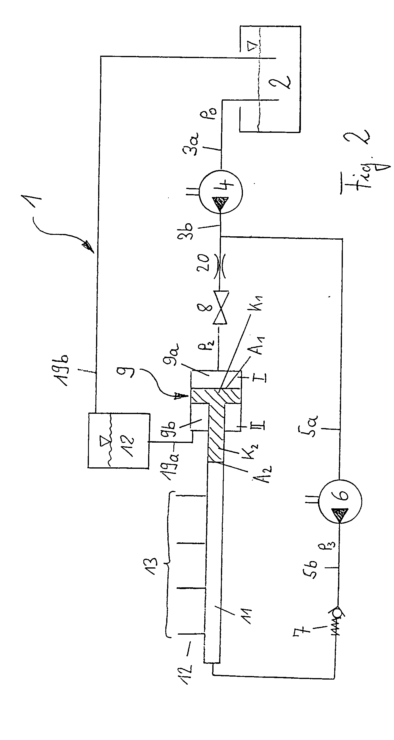
[0018] The fuel supply system 1 shown in FIG. 1 comprises a fuel tank 2, which is in communication with a low pressure fuel supply pump 4, a hydraulic transmission 9, which is a pressure increasing device and a high-pressure pump 6. The fuel supply pump 4 is connected with its inlet side to the fuel tank 2 by a line 3a and with its outlet side, by way of the line 3b, to the hydraulic transmission 9 and also, via a branch line 5a, to the high pressure pump 6.

[0019]FIG. 1 further shows a high pressure rail 11 by way of which the injectors 13 or injection nozzles are connected in parallel. The high pressure pump is connected to the high pressure rail by way of a line 5b and the hydraulic transmission 9 is connected to the high pressure rail via a line 10. In the connecting line 5b of the high pressure pump 6 to the high pressure rail 11, a check valve 7 is preferably arranged.

[0020] The connecting line 3b between the outlet of the fuel supply pump 4 and the hydraulic transmission 9 i...


PUM


Abstract

In a fuel supply system for an internal combustion engine with direct fuel injection including a fuel supply pump and, downstream thereof, a high pressure pump for supplying high pressure fuel to a plurality of injectors and, parallel to the high pressure fuel pump, a hydraulic transmission operated by the low pressure fuel of the fuel supply pump for generating initially high pressure fuel to the fuel injectors so as to permit instant engine startup upon actuation of a valve disposed in the fuel supply line from the fuel supply pump to the hydraulic transmission.

Description

[0001] This is a Continuation-In-Part Application of International Application PCT / EP03 / 13069 filed Nov. 21, 2003 and claiming the priority of German application 102 60 775.3 filed Dec. 23, 2002. BACKGROUND OF THE INVENTION [0002] The invention relates to a fuel supply system for an internal combustion engine with direct fuel injection including a fuel supply pump and downstream thereof a high pressure pump for supplying the fuel to a plurality of injectors and, parallel to the high pressure pump, a hydraulic transmission for providing in the start up phase an increased fuel pressure. [0003] Internal combustion engine with direct fuel injection require already during startup high fuel injection pressures in order to achieve a mixture of the fuel with the combustion air sufficient for ignition of the mixture. The minimum pressure of the fuel for gasoline engines with direct fuel injection is about 50 bar and for diesel engines with direct fuel injection it is about 120 bar. [0004] Th...

Claims


Application Information

Patent Timeline
Patent Type & Authority Applications(United States)
IPC IPC(8): F02M55/02F02M59/10F02M63/00F02M63/02
CPCF02M55/025F02M59/105F02M63/02F02M59/447F02M63/028F02M2200/60F02M63/0225
Inventor FREISINGER, NORMANN
Owner DAIMLER AG
Why Eureka
Try Eureka