Inflatable sealing valve, deflation sealing valve and sealing chamber of a sealed cabin

An inflatable sealing and sealing cabin technology, applied in the field of deflated sealing valves and sealing cabins, can solve the problems of interfering with the tracking, locking and guiding functions of photoelectric sensors, electrochemical reaction corrosion of metal contact surfaces, and water vapor pouring into equipment, so as to improve self-efficacy Protection function and value, avoid pitting or scratching, easy disassembly effect

Active Publication Date: 2019-04-09
THE THIRD RES INST OF CHINA ELECTRONICS TECH GRP CORP
View PDF8 Cites 0 Cited by
  • Summary
  • Abstract
  • Description
  • Claims
  • Application Information

AI Technical Summary

Problems solved by technology

[0004] The existing sealing means of the airtight cabin are mainly suitable for the dry environment on land. In the harsh environment at sea, the electrochemical reaction corrosion occurs on the metal contact surface, which leads to the problem that the equipment in the airtight cabin is easily filled with water vapor due to the impact of the surge. ; When the temperature (humidity) changes, there will be condensed salt mist inside, which seriously interferes with the tracking, locking and guiding functions of the photoelectric sensor; increase, and at the same time brought a lot of inconvenience in the harsh offshore environment

Method used


Image

  • Inflatable sealing valve, deflation sealing valve and sealing chamber of a sealed cabin
  • Inflatable sealing valve, deflation sealing valve and sealing chamber of a sealed cabin
  • Inflatable sealing valve, deflation sealing valve and sealing chamber of a sealed cabin

Examples


Embodiment Construction

[0036] The present invention will be described in detail below in conjunction with the implementations shown in the drawings, but it should be noted that these implementations are not limitations of the present invention, and those of ordinary skill in the art based on the functions, methods, or structural changes made by these implementations Equivalent transformations or substitutions all fall within the protection scope of the present invention.

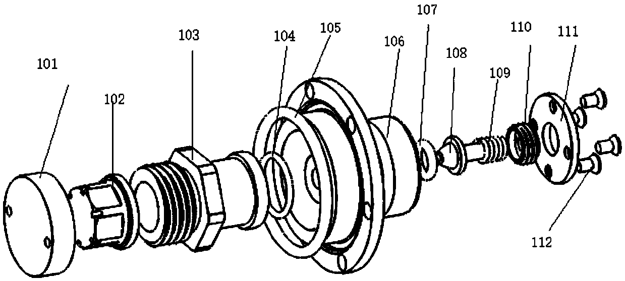
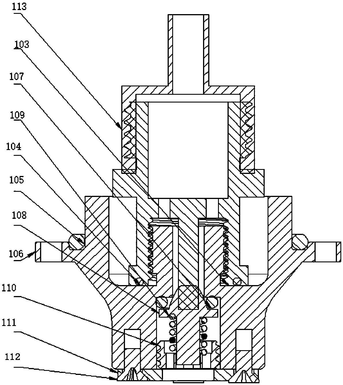
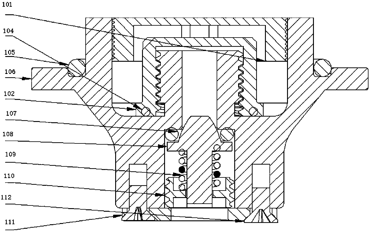
[0037] In one embodiment, an air-tight sealing valve for a sealed cabin includes a second sealing ring 105 and a first housing 106, the second sealing ring 105 is sleeved in the outer edge groove of the first housing 106, and the The first housing 106 is connected to the sealed cabin body; it also includes an inflatable sealing unit, a first cover 111 and a first sealing assembly; the inflatable sealing unit is placed in the inner hole of the first housing 106, and the first housing 106 and The inflatable sealing unit is connected...


PUM


Abstract

The invention relates to an inflation sealing valve of a sealed cabin. A first seal ring is connected to an inner bore groove of the outer side of a first shell in a sleeved mode. A first sealing blocking cap is connected with the inner bore groove of the outer side of the first shell. A first sealing cover is connected with the first sealing blocking cap. The invention further relates to a deflation sealing valve and the sealed cabin. The inflation sealing valve and the deflation sealing valve of the sealed cabin are both mounted in a sealed cabin body. Through the inflation sealing valve, gas can be rapidly and directly inflated into the sealed cabin, and the sealed cabin can be instantly sealed after stop of inflation. The deflation sealing valve has the internal overpressure protectivecapability. The sealed cabin is good in sealing structure and prevents water vapor inflowing. The inflation sealing valve and the deflation sealing valve are each designed into an integrated assemblyand are convenient and fast to dismantle. All components are designed through general modularization. All the independent components can be replaced quickly to facilitate later maintenance.

Description

technical field [0001] The invention belongs to the technical field of gas sealing, and in particular relates to an inflatable sealing valve, a leaking sealing valve and a sealing cabin. Background technique [0002] Generally, the sealing maintenance methods of the air-inflated and deflated air-tight valves of the airtight cabin mainly include extrusion friction sealing and sliding friction sealing. Although there are differences in various sealing structures, they all achieve the effect of isolation and sealing by means of the frictional contact pressure of the extruded contact surface being greater than the real-time pressure inside the sealed cabin. A special spring with a certain length and stiffness is used to reversely squeeze and push the sealing ring and the internal contact of the sealing valve housing to form a pair of frictional contact pairs to realize the local surface pressure increase, thereby realizing the gas-tight operation inside the sealing cabin. The e...

Claims


Application Information

Patent Timeline
Patent Type & Authority Patents(China)
IPC IPC(8): F16K24/06F16K27/08
CPCF16K24/06F16K27/08
Inventor 田洪宝轩新想温明
Owner THE THIRD RES INST OF CHINA ELECTRONICS TECH GRP CORP
Why Eureka
Try Eureka