Apparatus and method for mixing by agitation in a multichambered mixing apparatus including a pre-agitation mixing chamber

a multi-chamber, mixing apparatus technology, applied in the direction of dissolving with driven stirrers, multi-stage water/sewage treatment, separation processes, etc., can solve the problems of difficult re-dissolving of lumps in liquid, mixing often does not achieve the quality desired, and achieves the effect of superior ability to uniformly mix powder

Inactive Publication Date: 2006-08-15
REICA KOGYO kk
View PDF66 Cites 58 Cited by
  • Summary
  • Abstract
  • Description
  • Claims
  • Application Information

AI Technical Summary

Benefits of technology

[0011]The present invention, which was conceived in view of the problem explained above, provides a versatile apparatus and method for mixing powder and liquid by agitation, one in which combinations of powder and liquid to be mixed are substantially unlimited, and which provides a superior ability to uniformly mix powder and liquid.

Problems solved by technology

In mixing processes which include adding a liquid to a powder, adding a powder to a liquid, or simultaneously adding a powder and a liquid, secondary agglomerates (“lumps”) of the powder are often produced in the liquid, and, once they have been produced, it is usually extremely difficult to re-dissolve these lumps in the liquid.
However, because in any one of the above mixing devices and mixing methods the uniformity of the mixing is inadequate, or the available combination of powder and liquid to be mixed is limited, the mixing often does not achieve the quality desired.

Method used


Image

  • Apparatus and method for mixing by agitation in a multichambered mixing apparatus including a pre-agitation mixing chamber
  • Apparatus and method for mixing by agitation in a multichambered mixing apparatus including a pre-agitation mixing chamber
  • Apparatus and method for mixing by agitation in a multichambered mixing apparatus including a pre-agitation mixing chamber

Examples


embodiment 1

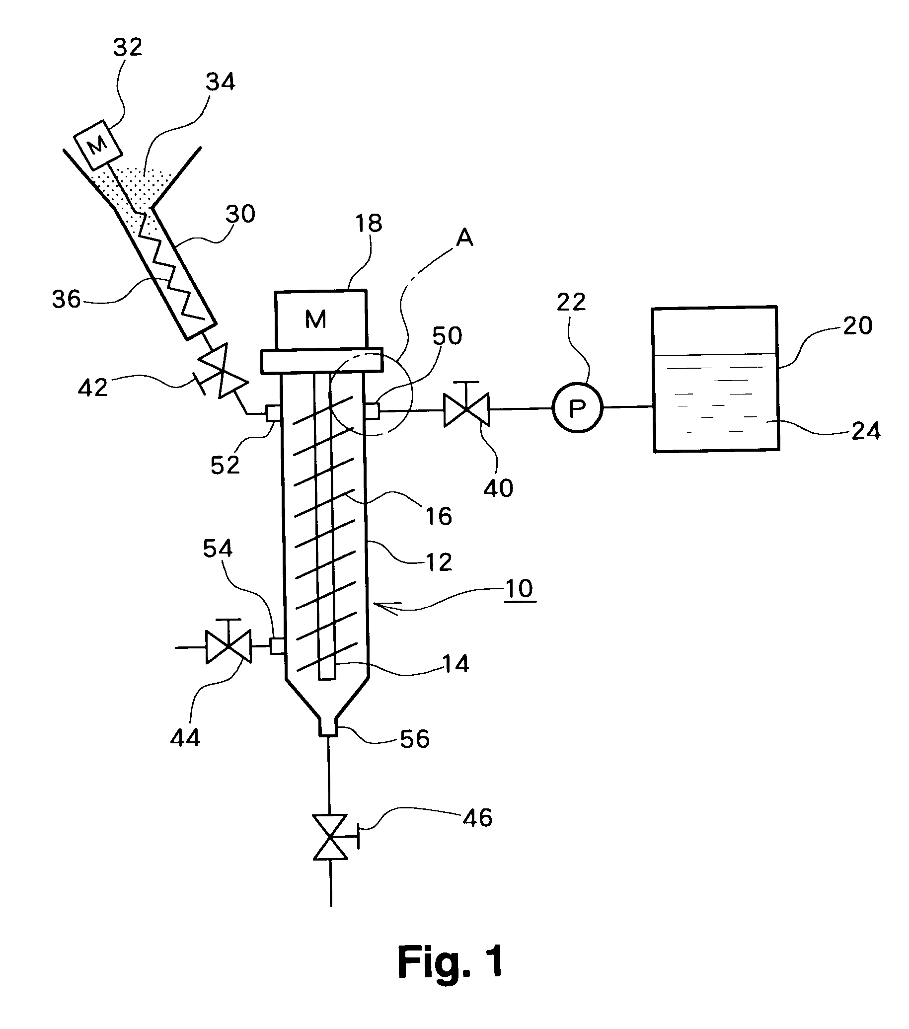
[0060]As shown in FIG. 1, an apparatus for mixing powder and liquid by agitation 10 (hereinafter referred to as an “agitation mixer 10”) according to the present embodiment comprises a casing 12 including a flow channel in which fluid passes through. In the casing 12, an agitation body consisting of a shaft 14 connected to a motor 18 of a vibration source and an agitation blade 16 attached to the perimeter of the shaft 14 is provided.

[0061]A powder inlet 52 for feeding a powder 34 into the casing 12 is mounted on an upper part of the casing 12, and a liquid inlet 50 for feeding a liquid 24 into the casing 12 is also mounted on the upper part of the casing 12 in the vicinity of the powder inlet 52. In this manner, the supplied powder contacts with the supplied liquid, which suppresses further generation of secondary agglomerate.

[0062]The liquid inlet 50 is connected, via a valve 40 and a pump 22, to a liquid reservoir 20 in which the liquid 24 to be mixed is stored. On the other hand...

embodiment 2

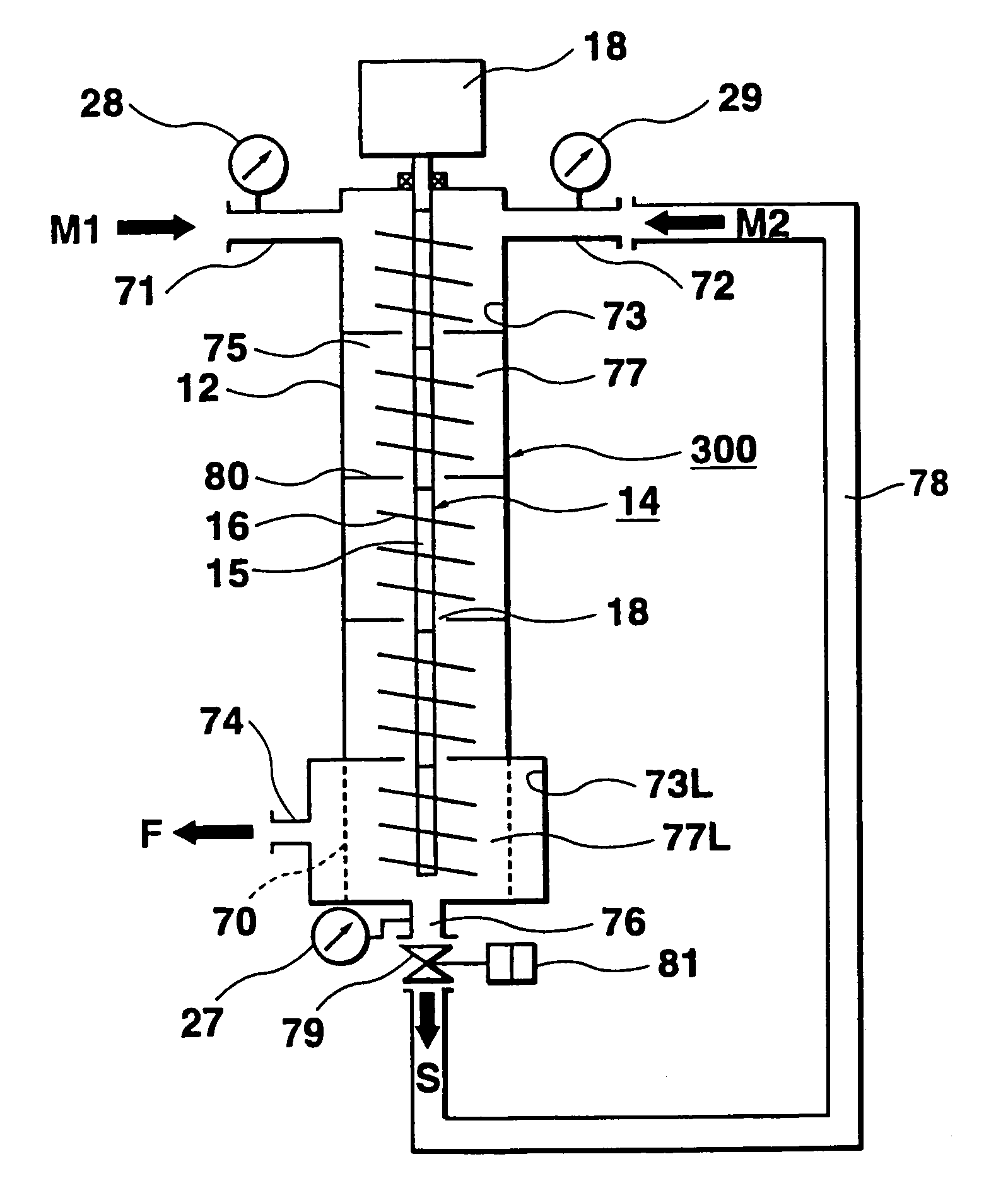
[0067]According to a second embodiment of the present invention, in the agitation mixer shown in FIG. 1, the supply port 56 is connected to the pump 22 and the liquid reservoir 20 through the valve 46 and used instead of the liquid inlet 50, the supply port 54 is connected to the powder inlet duct 30 through the valve 44 and used instead of the powder inlet 52, and the liquid inlet 50 as described in the first embodiment is used as a drain port through which the mixture of the liquid 24 and the powder 34 is ejected. Because components other than those described above in the second embodiment correspond to the components of the agitation mixer according to the first embodiment, corresponding components are identified by the same reference number or character, and their description is not repeated.

[0068]By feeding the powder 34 and the liquid 24 into the casing 12 from bottom, the supplied powder 34 and the liquid 24 are agitated by vibration while working against gravity, which cause...

embodiment 3

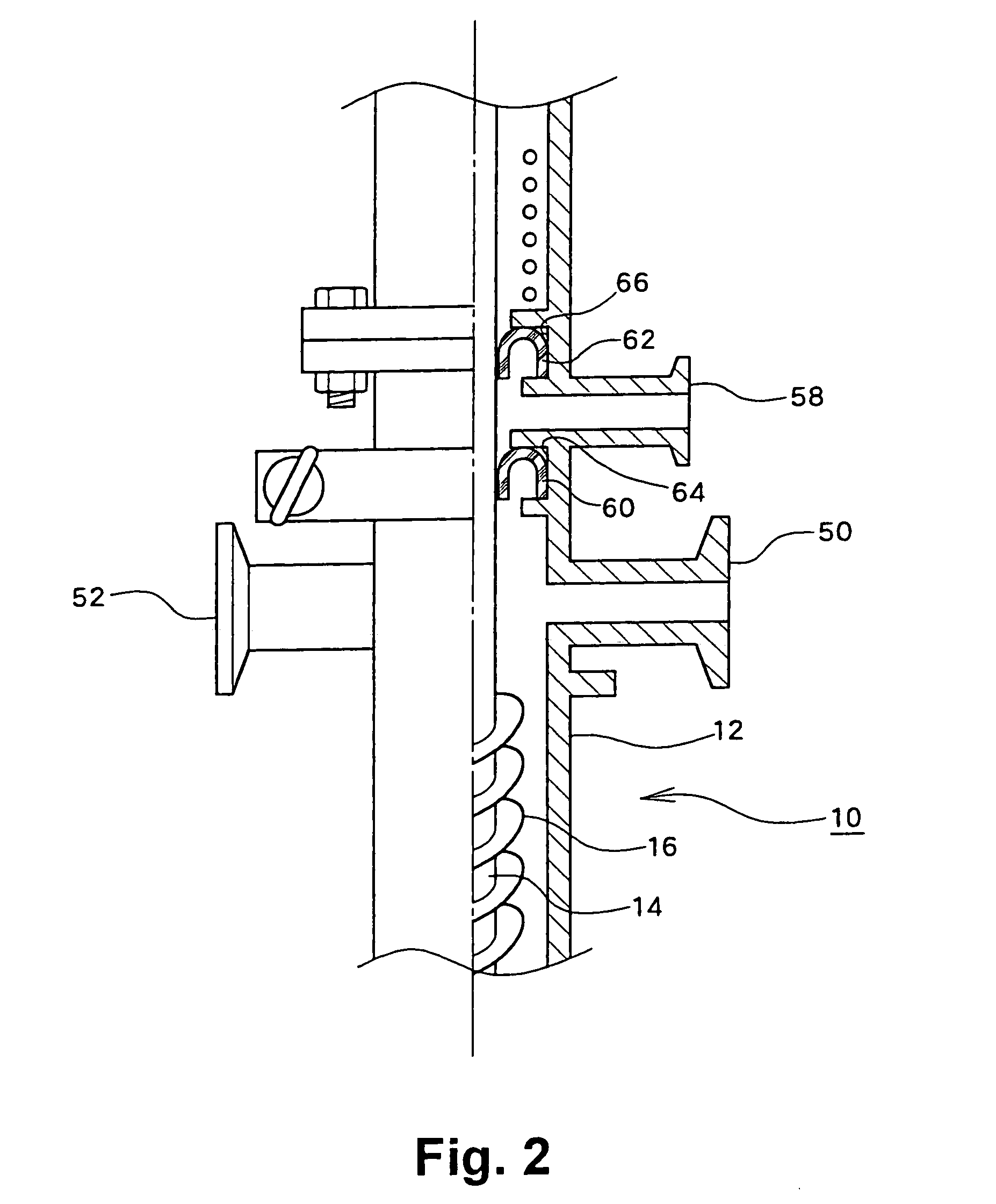
[0069]In a third embodiment, a supply port 58 shown in FIG. 2 is used in place of the liquid inlet 50 shown in FIG. 1 in the agitation mixer depicted in FIG. 1, while other components correspond to those in the agitation mixer according to the previous embodiment. As above, corresponding components are identified by the same references and their description is not repeated. This is also true in all following embodiments.

[0070]In the present embodiment, the casing 12 has a double packing structure in order to prevent fluid from entering into the motor being a vibration source for vibrating the agitation body from an agitation mixing area in the casing 12. More specifically, as shown in FIG. 2, the double packing structure is such that an inverted U-shape packing 60 is attached to a packing stuffing box 64 in the vicinity of the agitation mixing area, whereas in the vicinity of a coil provided near the motor, an inverted U-shape packing 62 is attached to a packing stuffing box 66. The...


PUM

PropertyMeasurementUnit
weight ratioaaaaaaaaaa
weight percentaaaaaaaaaa
thicknessaaaaaaaaaa

Abstract

An apparatus for agitation mixing comprises a casing 12 including a flow channel through which fluid passes, an agitation body consisting of a shaft 14 installed in the casing 12 and connected to a motor 18 and an agitation blade 16 mounted on the perimeter of the shaft 14, a powder inlet 52 attached to the casing 12 to feed a powder 34 into the casing 12, a liquid inlet 50 attached to the casing 12 in the vicinity of the powder inlet 52 to feed a liquid 24 into the casing 12, a powder inlet duct 30 connected to the powder inlet 52, and an introducer 36 placed in the powder inlet duct 30 and connected to a motor 32.

Description

BACKGROUND OF THE INVENTION[0001]1. Field of the Invention[0002]The present invention relates to an apparatus and method for mixing by agitation, and more particularly to an apparatus and method applicable to a wide variety of uses involving the mixing of a powder and a liquid by agitation.[0003]2. Description of the Related Art[0004]In mixing processes which include adding a liquid to a powder, adding a powder to a liquid, or simultaneously adding a powder and a liquid, secondary agglomerates (“lumps”) of the powder are often produced in the liquid, and, once they have been produced, it is usually extremely difficult to re-dissolve these lumps in the liquid.[0005]Accordingly, in recent years apparatuses and methods for uniformly mixing powder and liquid while avoiding generation of secondary agglomerates during mixing of the powder and the liquid have been suggested.[0006]In Japanese Patent Laid-Open Publications No. Hei 11-19495, No. 2001-62273, and No. 2002-166154, a continuous m...

Claims


Application Information

Patent Timeline
Patent Type & Authority Patents(United States)
IPC IPC(8): B01F11/00B01F15/02B01F1/00B01F3/12B01F5/10B01F7/00B01F15/00
CPCB01F1/0011B01F3/1228B01F3/1271B01F7/00391B01F7/0045B01F11/0082B01F13/1044B01F15/00019B01F15/0251B01F3/1221B01F2015/00084B01F5/10B01F2001/0094B01F2003/0028B01F2013/1083B29B7/94B29B7/603B29B7/14B29B7/16B29B7/244B29B7/401B29B7/421B29B7/428B29B7/422B29B7/429B01F21/504B01F23/023B01F21/10B01F23/54B01F23/59B01F23/53B01F25/50B01F27/114B01F27/115B01F31/441B01F33/8305B01F35/145B01F33/83612B01F2035/351B01F35/71775
Inventor TANIGUCHI, TORU
Owner REICA KOGYO kk
Why Eureka
Try Eureka