Printed monopole multi-band antenna

a multi-band, printed technology, applied in the structure of radiating elements, elongated active elements, resonance antennas, etc., can solve the problems of not being required to provide tri-band matching circuits, expensive and area-consuming matching circuits, etc., to improve area consumption efficiency, reduce manufacturing costs, and improve area consumption

Inactive Publication Date: 2006-08-15
KYOCERA CORP
View PDF9 Cites 21 Cited by
  • Summary
  • Abstract
  • Description
  • Claims
  • Application Information

AI Technical Summary

Benefits of technology

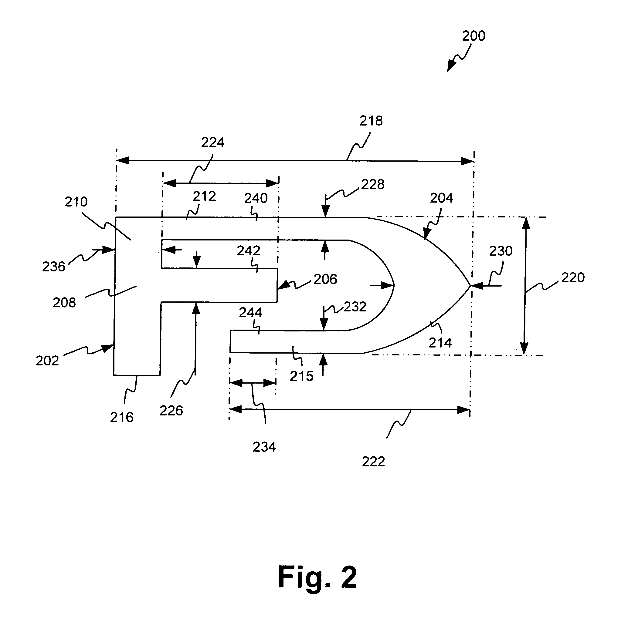
[0009]According to one particular embodiment, the first radiator arm comprises a plurality of segments connected in series, at least one of the plurality of segments angled with respect to another one of the plurality of segments. For example, the first radiator arm may include a first segment connected to the common radiator element, a second segment connected to the first segment, a third segment connected to the second segment, and a fourth segment connected to the third segment, wherein the first, second, third and fourth segments of the first radiator arm are arranged to fold around the second radiator arm along substantially a single plane, thereby improving area consumption efficiency. Typically, electromagnetic coupling between the second radiator arm and at least one of the first, second, third and fourth segments of the first radiator arm contributes to or otherwise affects the resonance of the first radiator arm.
[0010]According to various embodiments of the invention, one or more of the following benefits may be realized by the multi-band antenna including, for example, reduced manufacturing costs, reduced area consumption, reduced device size, and improved multiple frequency band support. For example, according to one embodiment, expensive and area consuming matching circuits are not required to provide tri-band support.

Problems solved by technology

For example, according to one embodiment, expensive and area consuming matching circuits are not required to provide tri-band support.

Method used


Image

  • Printed monopole multi-band antenna
  • Printed monopole multi-band antenna
  • Printed monopole multi-band antenna

Examples


Embodiment Construction

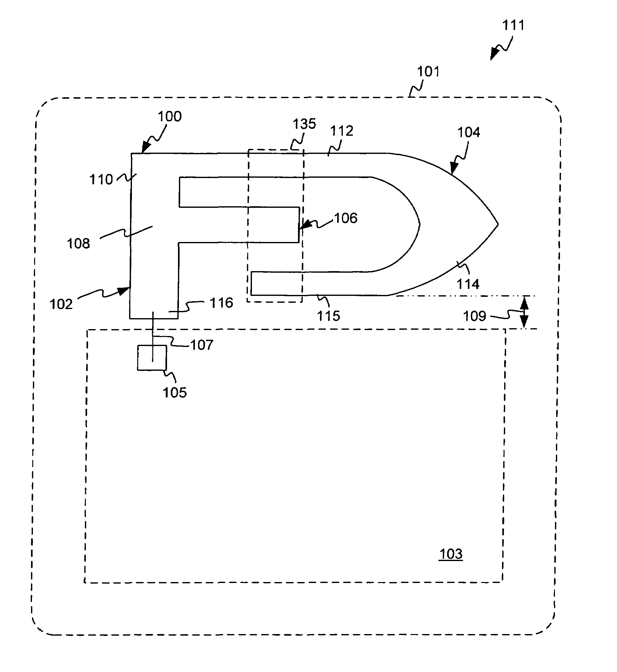
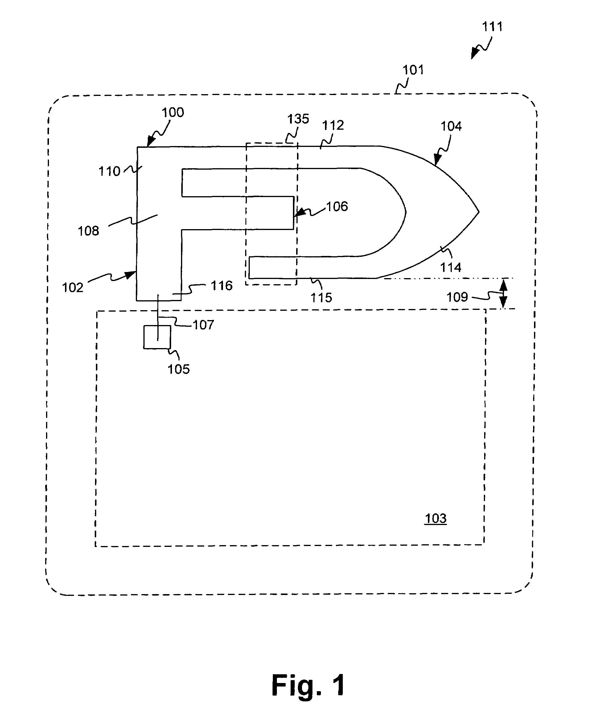
[0015]Referring first to FIG. 1, there is shown exemplary multi-band antenna 100 printed on housing 101 of wireless communication device 111 according to one embodiment of the present invention. By way of example, wireless communication device 111 may be a mobile phone capable of communicating RF signals in one or more frequency bands. According to one particular embodiment, multi-band antenna 100 is capable of resonating in the cellular (or Advance Mobile Phone Service (“AMPS”)) band of 824 to 894 megahertz (MHz), the Personal Communication Service (“PCS”) band of 1850 to 1990 MHz, and receiving global positional satellite (“GPS”) signals in the band of 1565 to 1585 MHz.

[0016]As shown in FIG. 1, multi-band antenna 100 is printed on housing 101. More particularly, multi-band antenna 100 comprises a folded monopole antenna comprising common radiator element 102, first radiator arm 104 and second radiator arm 106. Each of common radiator element 102, first radiator arm 104 and second ...


PUM


Abstract

An exemplary printed monopole multi-band antenna comprises a common radiator element, a first radiator arm connected to the common radiator element and a second radiator arm connected to the common radiator element. Electromagnetic coupling between the first radiator arm and the second radiator arm contributes to and / or shifts the resonance of the first radiator arm and the second radiator arm, thereby allowing the multi-band antenna to be tuned such that the first radiator arm is capable of resonating at a first frequency range and at a second frequency range, and the second radiator arm is capable of resonating at a third frequency range.

Description

BACKGROUND OF THE INVENTION[0001]1. Field of the Invention[0002]The present invention relates to the field of wireless communication devices. More specifically, the invention relates to antennas for wireless communication devices.[0003]2. Related Art[0004]A typical wireless communication device, such as a mobile phone, comprises, among other things, a processor coupled to a memory and to a transceiver, each enclosed in a housing. A mobile power source, such as a battery, is coupled to and supplies power to the processor, the memory and the transceiver. A speaker and a microphone are also enclosed within the housing for transmitting and receiving, respectively, acoustic signals to and from a user of the wireless communication device. The wireless communication device communicates information by transmitting and receiving electromagnetic (“EM”) energy in the radio frequency (“RF”) band via an antenna coupled to the transceiver.[0005]More recently, the demand for wireless communication...

Claims


Application Information

Patent Timeline
Patent Type & Authority Patents(United States)
IPC IPC(8): H01Q1/38H01Q1/24H01Q5/00H01Q5/371H01Q9/42
CPCH01Q1/243H01Q5/371H01Q9/42H01Q1/38
Inventor FABREGA-SANCHEZ, JORGE
Owner KYOCERA CORP
Why Eureka
Try Eureka