Distributed control system

a control system and distribution technology, applied in the field of control systems, can solve the problems of switching the light in the room no longer being able to control the switch, the single point of failure of a central processing unit, and the single point of failure of a network

Active Publication Date: 2006-08-15
LIQUID SKY STUDIOS
View PDF12 Cites 88 Cited by
  • Summary
  • Abstract
  • Description
  • Claims
  • Application Information

AI Technical Summary

Problems solved by technology

Dependence on a central processing unit creates a single point of failure.
Because control is not localized, the network becomes another single point of failure.
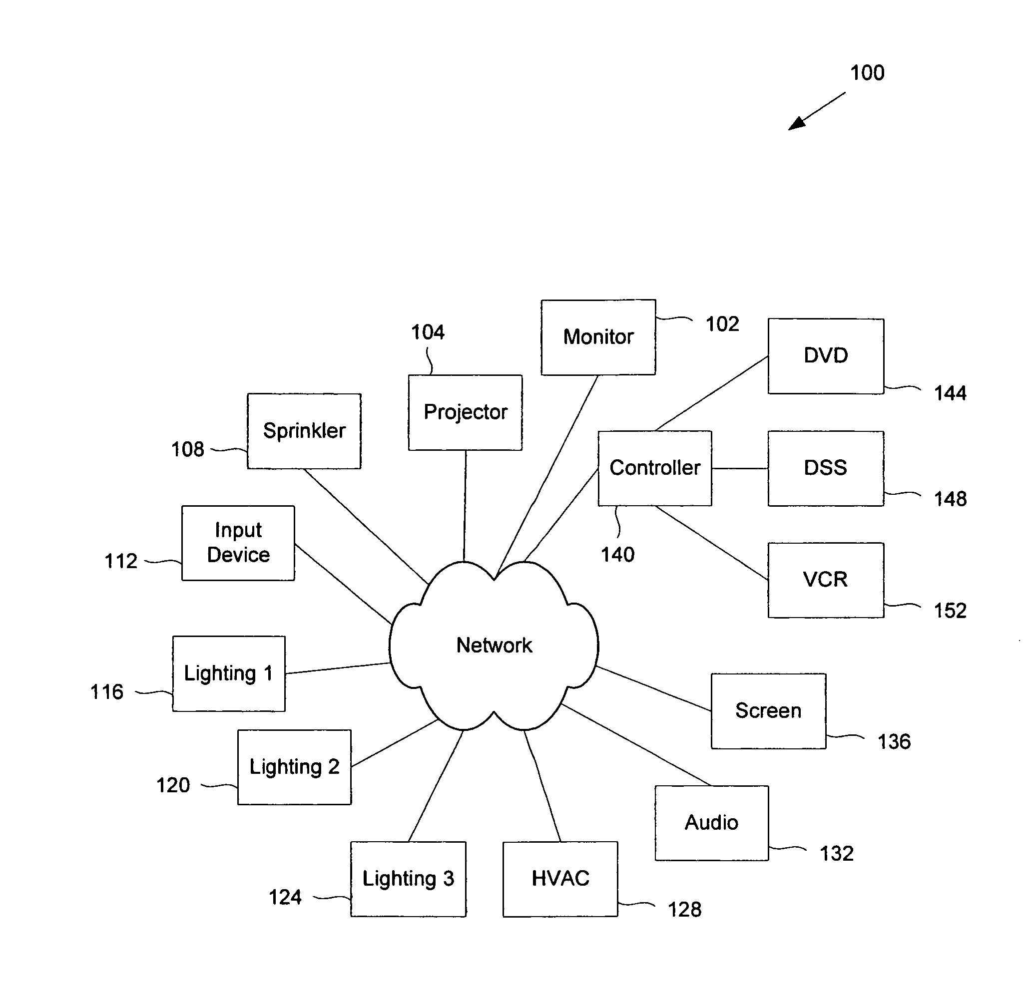
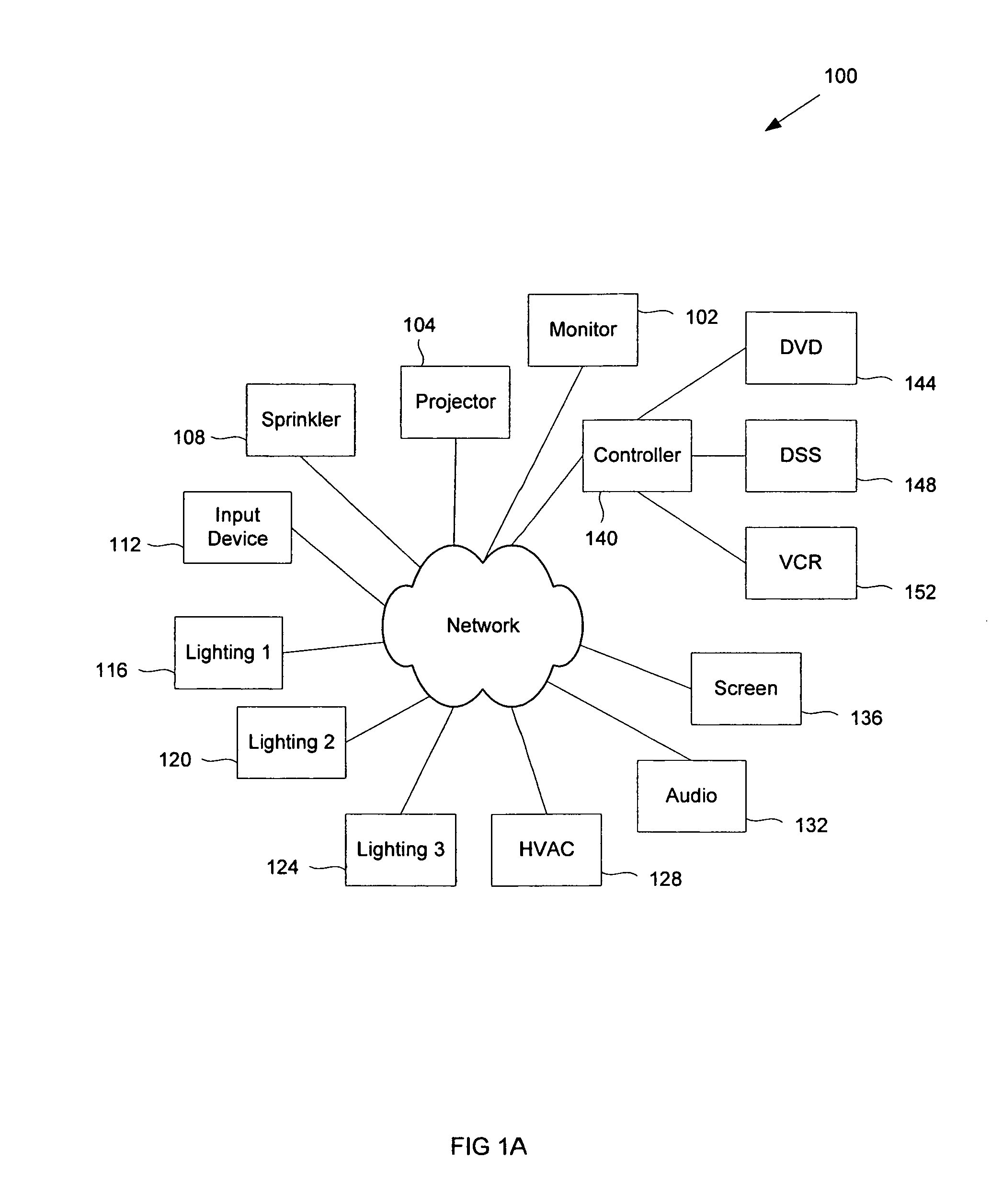
For example, if there is a switch that controls lights in a room, and there is a network failure between the switch and the central processing unit, the switch can no longer control the lights in the room.
This creates a large increase in the amount and complexity of the electrical wiring in a building.
Because of the cost and complexity of the wiring, most implementations are wired so that related fixtures are all wired together on one lighting circuit.
This leaves little room for flexibility in the system once it is fully installed.

Method used


Image

  • Distributed control system
  • Distributed control system
  • Distributed control system

Examples


Embodiment Construction

[0016]The invention can be implemented in numerous ways, including as a process, an apparatus, a system, a composition of matter, a computer readable medium such as a computer readable storage medium or a computer network wherein program instructions are sent over optical or electronic communication links. In this specification, these implementations, or any other form that the invention may take, may be referred to as techniques. In general, the order of the steps of disclosed processes may be altered within the scope of the invention.

[0017]A detailed description of one or more embodiments of the invention is provided below along with accompanying figures that illustrate the principles of the invention. The invention is described in connection with such embodiments, but the invention is not limited to any embodiment. The scope of the invention is limited only by the claims and the invention encompasses numerous alternatives, modifications and equivalents. Numerous specific details ...


PUM


Abstract

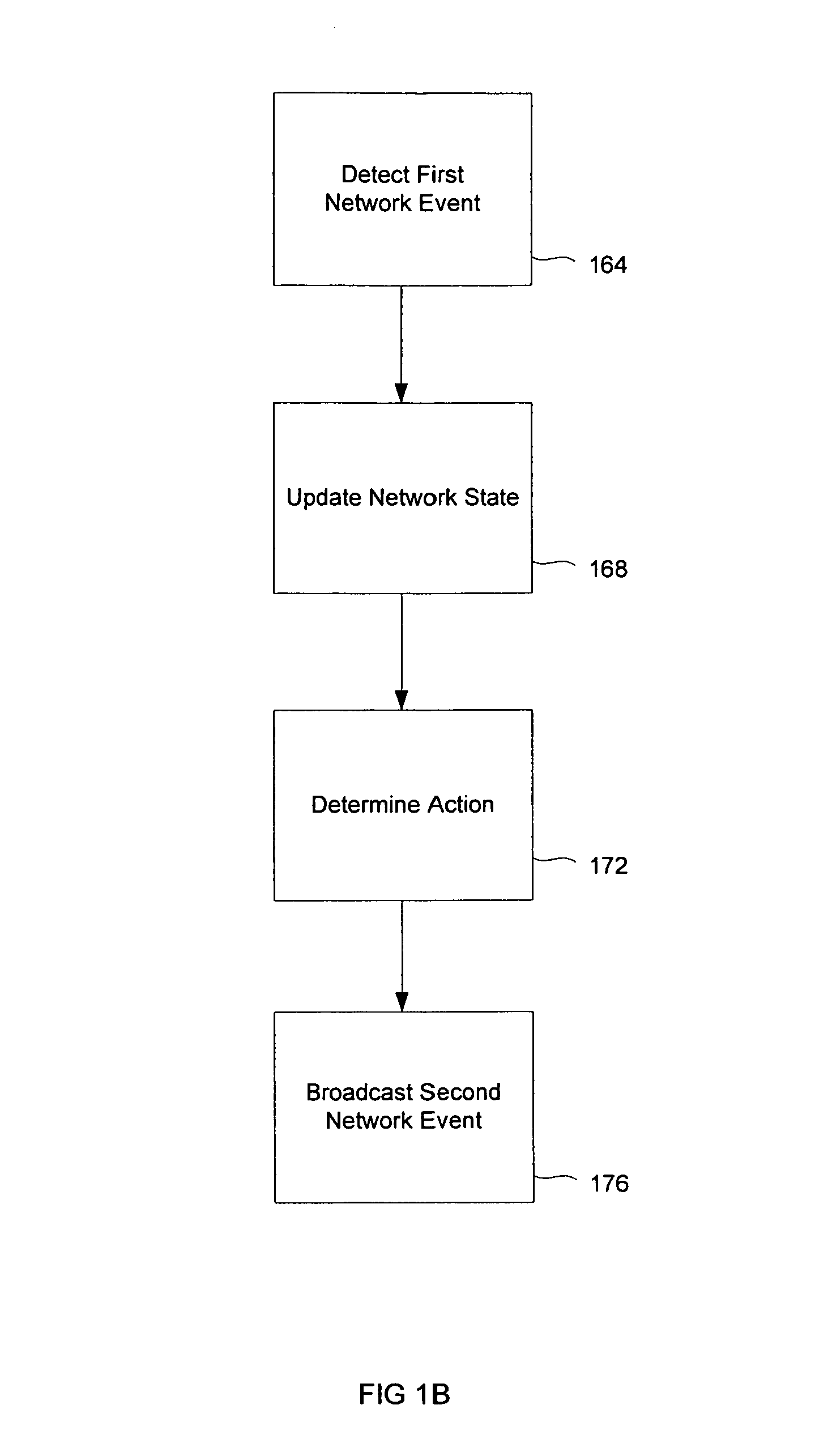
A technique is disclosed for controlling a plurality of devices in a building. The technique includes detecting a first network event at a first device, updating a network state on the first device based on the first network event, determining at the first device an action based on the network state, and transmitting a second network event to a second device.

Description

FIELD OF THE INVENTION[0001]The present invention relates generally to control systems. More specifically, controlling a plurality of devices in a building is disclosed.BACKGROUND OF THE INVENTION[0002]Control systems provide electronic control of home or office devices, such as lighting and distributed audio systems. Most existing systems include a central processing unit. Dependence on a central processing unit creates a single point of failure. Because control is not localized, the network becomes another single point of failure. For example, if there is a switch that controls lights in a room, and there is a network failure between the switch and the central processing unit, the switch can no longer control the lights in the room.[0003]All devices being controlled are wired back to the central processing unit. For example, in an electronically controlled building, each lighting circuit must have its own electrical wiring all the way back to the dimming module. This creates a lar...

Claims


Application Information

Patent Timeline
Patent Type & Authority Patents(United States)
IPC IPC(8): G05B13/02
CPCG05B19/042G05B2219/25011
Inventor LABUDA, DAVID S.
Owner LIQUID SKY STUDIOS
Why Eureka
Try Eureka