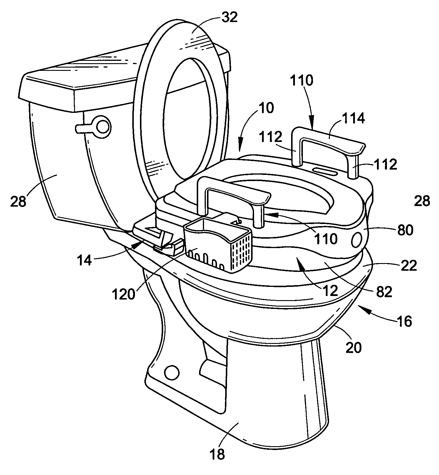
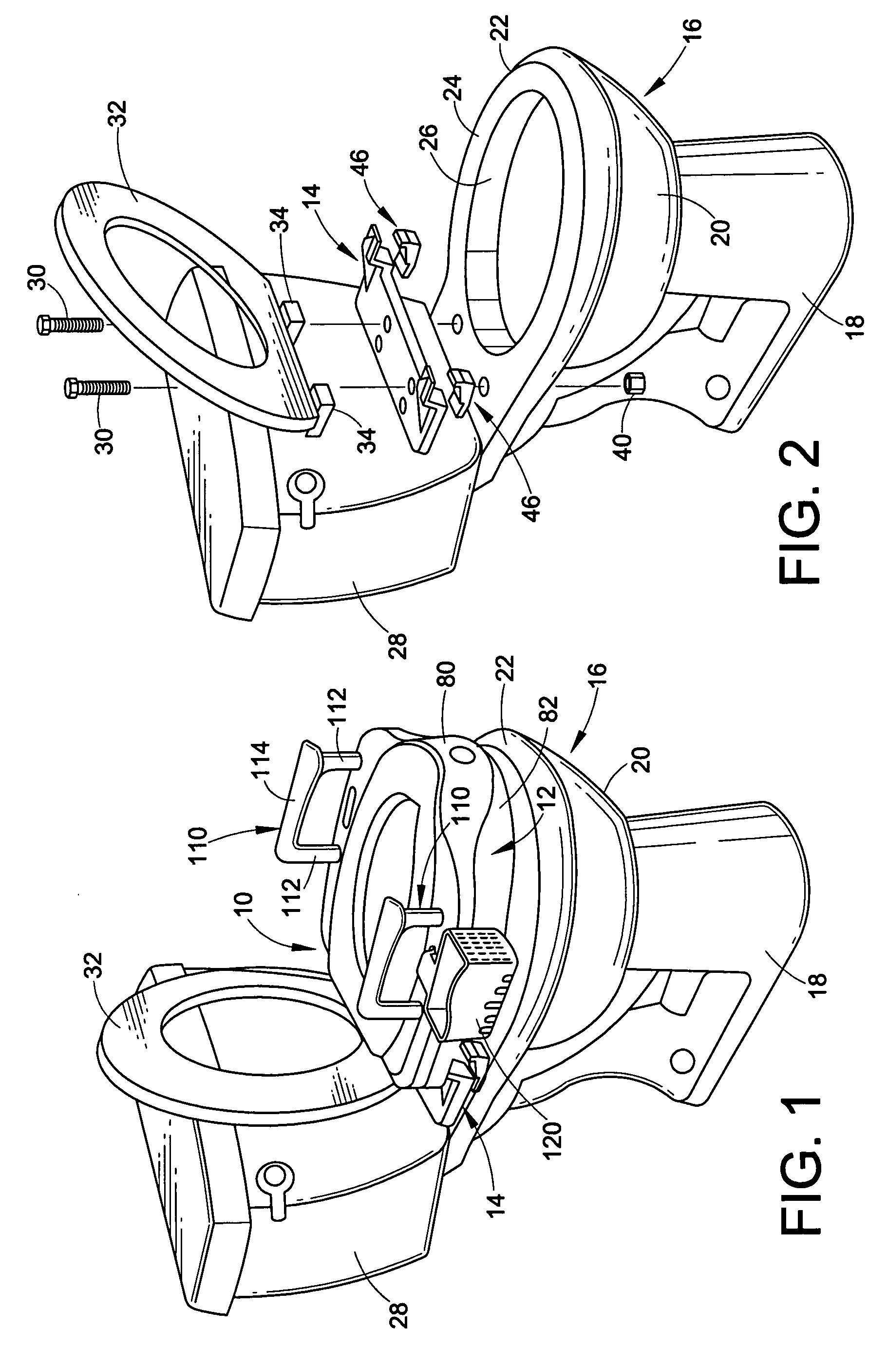
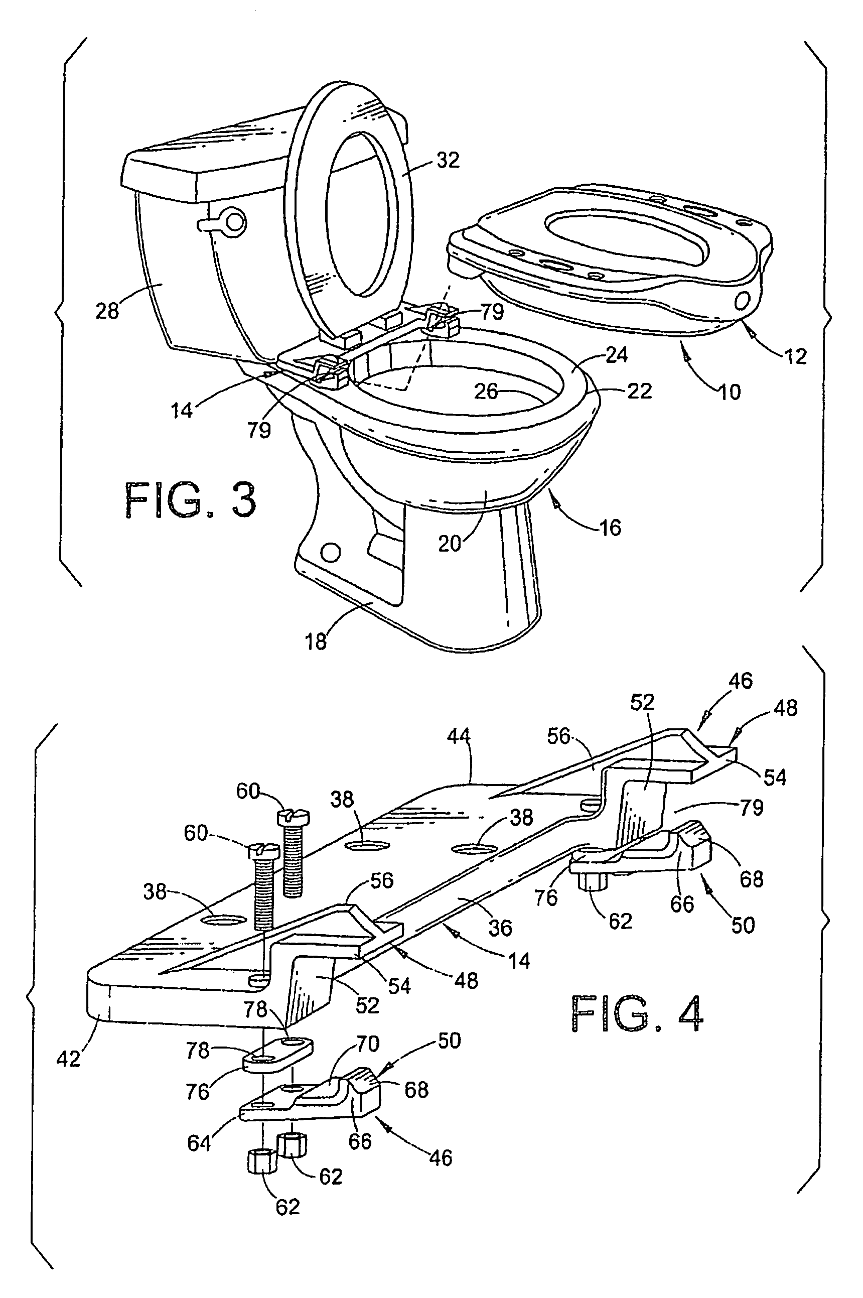
[0026]FIGS. 1–3 illustrate the elevated toilet seat assembly of the present invention generally at 10. The toilet seat assembly has two major components, a seating ring 12 and a mounting bracket 14. The seating ring 12 has the usual shape and dimensions for supporting a user on a toilet. The mounting bracket 14 is attached to a toilet bowl. The seating ring 12 is removably mountable on the toilet bowl and is retained thereon by releasable engagement with the mounting bracket 14. This engagement will be explained further below.
[0027]FIG. 2 shows a conventional toilet 16 and the mounting bracket 14 installed thereon. The toilet includes a base 18 supporting a bowl 20. The top of the bowl has an upper rim 22 that includes a top land 24. The rim defines an opening 26 which in this case has an oval shape. The oval opening has a major diameter and a minor diameter. The bowl 20 may be connected to the usual water closet shown at 28. The mounting bracket 14 rests on the top land 24 of the rim at the rear edge thereof. It is retained in place by bolts 30. As shown in this embodiment the bolts 30 may also mount a conventional toilet seat 32. The hinges 34 of the seat 32 may rest on top of the bracket 14 and the bolts 30 extend through the hinges to retain the conventional seat.
[0028]Details of the mounting bracket 14 are evident in FIGS. 4–8. The mounting bracket 14 is an elongated plate having a central, relatively flat body or base portion 36. Mounting holes 38 are formed in the body portion. These holes 38 are located on the same template as the standard holes in the toilet bowl rim 22 so that holes 38 will line up with the holes in the bowl. Bolts 30 (FIG. 2) extend through these holes 38 and are retained by nuts 40 to fasten the mounting bracket 14 to the toilet bowl 20. The mounting bracket further includes end portions 42, 44 which join the base portion 36. The length of the base portion 36 is such that the end portions 42, 44 are located beyond the outer perimeter of the toilet bowl when the mounting bracket is installed on a toilet bowl. This is important for providing a solid foundation for the attachment elements which will now be described.
[0029]Attached to the front edge of the end portions 42, 44 are two first attachment elements 46. Each first attachment element has a jaw 48 and a latch 50. The jaw is formed by an upright support 52 and a horizontal plate 54. As can be seen the support 52 extends upwardly from one of the end portions 42 or 44 and the plate 54 extends outwardly from the top edge of the support 52. The support 52 and plate 54 are reinforced by a gusset 56. Immediately behind the support 52 and on either side of the gusset 56 are a pair of holes 58. These receive attachment bolts 60 (FIG. 4) which, together with nuts 62, fasten the latch 50 to the underside of the end portion of the mounting bracket.
[0030]Details of the latch 50 are shown in FIGS. 9–11. The latch includes a base plate 64 and an upstanding pawl 66. The front edge of the pawl is beveled as at 68. A central ledge 70 is formed on the base plate and bolt holes 72 are formed in the plate behind the ledge. There are depressions 74 on the underside of the plate 64. An elastomeric spacer 76 has holes 78 therein aligned with the holes 72 and 58 for receiving the bolts 60. The spacer 76 provides a cushion between the latch 50 and the end portions 42, 44 to allow for some flexure of the latch during insertion and removal of the seating ring's attachment elements. It can be seen that the jaw and latch extend from the mounting bracket's end portions-in facing, spaced relation to one another that defines a receiving socket 79 (FIGS. 3 and 4) between them.
[0031]Turning now to the seating ring 12, FIGS. 5, 6 and 12–14 illustrate the details of the seating ring. The ring comprises two main parts, a shell 80 and a riser 82. The shell sits on top of the riser and is attached thereto or is integrally formed therewith. The shell is the portion of the seating ring which the user will contact. The shell 80 includes a generally oval upper seating surface 84 which defines a central opening 86. A front skirt 88 depends from the front edge of the seating surface 84. The skirt 88 and seating surface 84 merge with first and second flanges or wings 90, 92 on either side of the seating ring. The flanges extend outwardly from the seating surface 84 such that the flanges will lie substantially outside the perimeter of the toilet bowl rim 22 when the seat is mounted on the bowl 20.
[0032]As seen in FIG. 12, the riser 82 has a generally oval portion 94 joining a laterally extending shoulder 96 at the rear of the seating ring. The shoulder has formed therein two second attachment elements 98. The second attachment elements each include a receptacle 100 and a pocket 102, both formed as indentations in the shoulder 96. The receptacle and pocket define a bar or catch 104 between them. A lip 106 (FIG. 13) is formed on the underside of the catch for engagement with the pawl 66 of the latch 50. The latch 50 is flexible due to the movement allowed by the spacer 76. This movement allows the second attachment elements 98 to engage the first attachment elements 46 in a snap fit. This is done by inserting the jaws 48 into the receptacles 100 and pivoting the ring 12 down and back until the lip 106 slides up over the beveled edge 68 on the pawl 66 and snaps in behind the pawl. The pawl then resides in the pocket 102. To remove the ring 12, it is lifted until the catch 104 is released from the pawl 66 and then the ring can be pulled away from the toilet.
[0033]It will be noted that the oval portion 94 of the riser does not extend laterally underneath the flanges 90, 92 but instead follows the shape of the toilet bowl and thus, remains inside of the flanges. It can best be seen in FIG. 14 that the flanges 90, 92 are, in effect, cantilevered from the riser 82. The oval portion 94 also has two crescent-shaped extensions 108. Together the extensions define a partial oval that has a slightly reduced major and minor outer diameter compared to those of the oval portion 94. This permits the extensions 108 to fit inside the inner diameter of the toilet bowl's rim 22. Thus, the bottom surface of the oval portion 94 sits on the top land 24 of the toilet bowl rim while the extensions 108 fit just inside the rim 22. The extensions 108 extend slightly into the bowl in telescoping relation. The extensions therefore prevent the riser 82 from shifting laterally or otherwise slipping off the top of the bowl. The riser oval portion 94 can have a thickness (that is, a vertical height) of anywhere from an inch or so to six to eight inches or more, depending on the amount of elevation desired.
[0034]The flanges 90, 92 have a thickness that allows sufficient reinforcing ribs (not shown) on their underside so that the flanges can be weight bearing, i.e., a user can put his or her hands on the flanges to assist in lowering themselves or in standing up. Preferably the user will put his or her weight on a pair of arm rests, shown in FIG. 1 at 110. The arm rests have upright legs 112 with pegs of reduced diameter at the bottom of the legs. The tops of the legs are joined by a handle or grip portion 114. The pegs can be mounted in receptacles 116 (FIG. 5) that are formed in the flanges 90, 92. A user can put his or her hands on the handle grip portion 114 to push up from the seat, or to lower themselves onto the seat.
[0035]As seen in FIG. 5, the flanges 90, 92 each have a further central socket 118 that can receive a mounting bracket of an optional auxiliary basket 120. The basket includes a container portion. The basket's mounting bracket suspends the container over the side of the flanges 90, 92. The container can hold whatever items are desired to have conveniently stored nearby.
[0036]It can be seen that the elevated toilet seat as described provides several advantages for users who have difficulty sitting and standing. The riser 82 raises the height of the shell 80 so that a user need not sit as far down to be supported on the seating ring. This helps prevent accidents resulting from a user basically falling onto the toilet. Then, because the user is sitting up higher, there is less difficulty in standing up from the seat. The arm rests 110 also allow the user to use his or her arms to assist in rising to a standing position. Having the handles on the seat precludes the need to find a nearby structure on which to push off. The arrangement of the flanges and bracket helps distribute the load more evenly around the rim of the toilet. If a user is putting weight on the handles, much of that load is transferred to the mounting bracket 14 and thus to the rear edge of the toilet bowl.
[0037]It will be understood that the embodiments of the present invention which have been described are illustrative of some of the principles and applications of the present invention. Numerous modifications may be made by those skilled in the art without departing from the true spirit and scope of the invention. For example, while the first and second attachment elements are shown as a male clamping arrangement received in a female catch, the attachment elements could have other configurations of interengaging members. It is preferred that the attachment elements not involve any separate fasteners such as bolts, pins or the like.