Auxiliary power unit with an oil-free compressor

a compressor and auxiliary power technology, applied in the direction of engine starters, turbine/propulsion engine ignition, machines/engines, etc., can solve the problems of increasing the life requirements of aircraft components, conventional sealing, and insufficient life to meet the current oil-free environment standard

Active Publication Date: 2006-08-22
HAMILTON SUNDSTRAND CORP
View PDF17 Cites 23 Cited by
  • Summary
  • Abstract
  • Description
  • Claims
  • Application Information

AI Technical Summary

Problems solved by technology

Furthermore, aircraft component life requirements have been increased to the point where conventional seals used to isolate machinery oil and oil vapours from cabin air do not have sufficient life to meet the current oil-free environment standard.
Unfortunately, the face type seals wear at such a rate that the lubrication oil for the APU gears and bearings eventually migrates into the cabin air between normally scheduled APU overhauls.

Method used


Image

  • Auxiliary power unit with an oil-free compressor
  • Auxiliary power unit with an oil-free compressor

Examples


Embodiment Construction

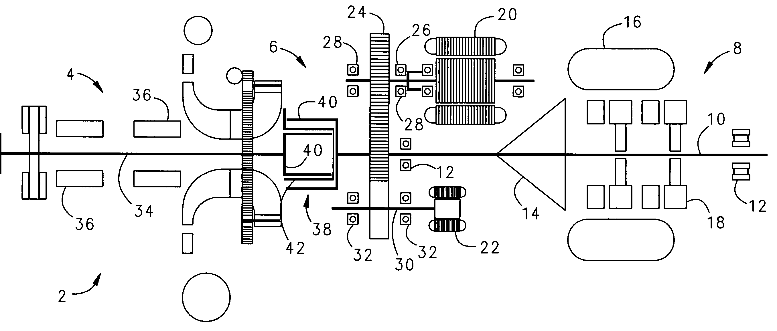
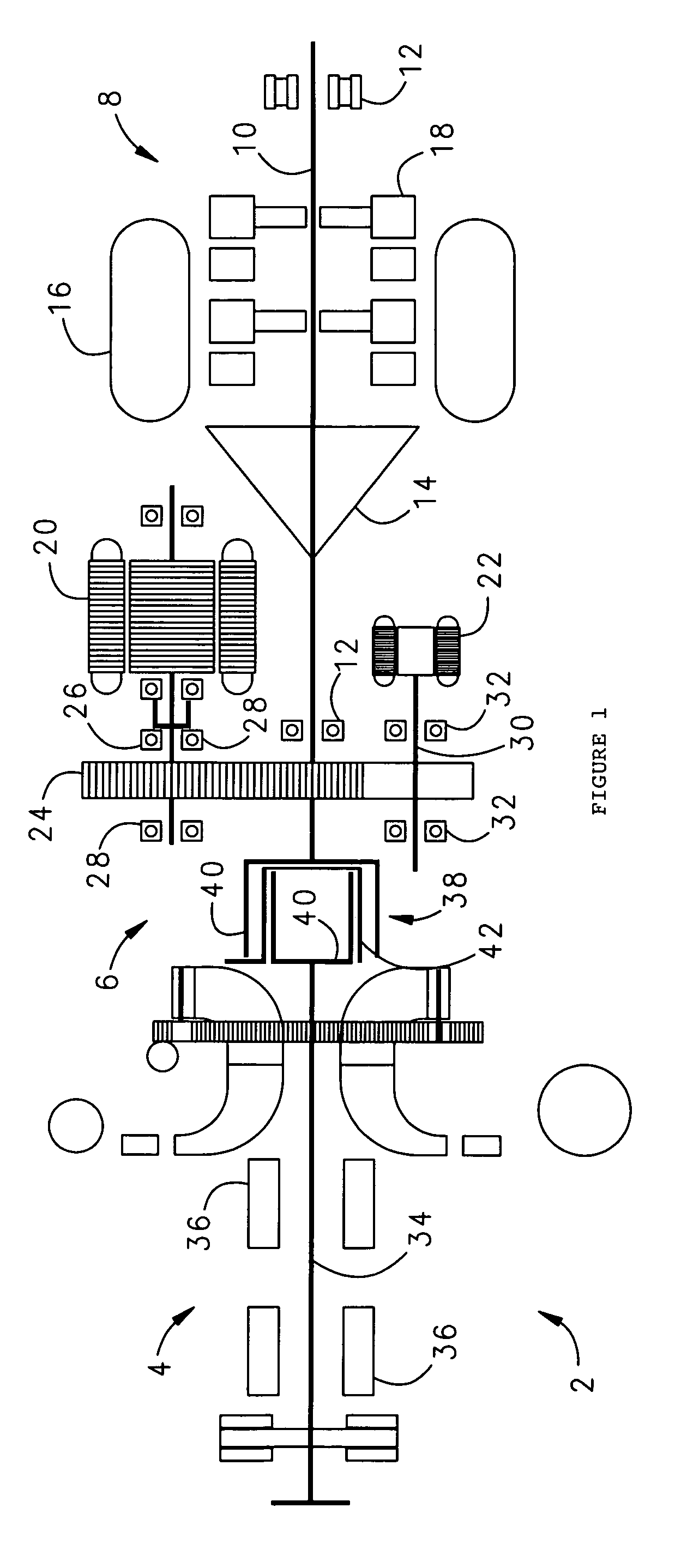
[0008]FIG. 1 is a side cut-away view of an APU 2 with an oil-free load compressor 4 according to a preferred embodiment of the invention. The load compressor 4 is mounted on one side of a conventional APU gearbox 6 opposite another side of the gearbox 6 to which a conventional APU power head 8 is mounted. In this configuration, the load compressor 4 is driven at the same shaft speed as the power head 8.

[0009]According to the prior art, it has been usual practice to couple the load compressor 4 to the gearbox 6 on the same side of the gearbox 6 as the power head 8, with the load compressor 4 mounted on a common high-speed shaft 10 supported by high speed shaft bearings 12 with the power head 8. Locating the load compressor 4 on a side of the gearbox 6 opposite the power head 8 isolates the load compressor 4 from power head bearings 12 and lubrication oil for the power head 8.

[0010]The power head 8 is conventional, and comprises a cycle compressor 14, combustor 16 and drive turbine 18...


PUM


Abstract

An auxiliary power unit for aircraft with a load compressor that delivers cabin air free of oil contamination by supporting a drive shaft for the load compressor with oil-free bearings and coupling the load compressor to a gearbox and power head for the auxiliary power unit through a synchronous magnetic torque coupling on an opposite side of the gearbox to which the power is mounted.

Description

FIELD OF THE INVENTION[0001]The invention relates to a load compressor for an aeronautical gas turbine-powered auxiliary power unit (APU), and more particularly to an APU that comprises an oil-free load compressor for delivering cabin air to an aircraft.BACKGROUND OF THE INVENTION[0002]It has become increasingly necessary to improve the quality of cabin air delivered in passenger transport aircraft. Furthermore, aircraft component life requirements have been increased to the point where conventional seals used to isolate machinery oil and oil vapours from cabin air do not have sufficient life to meet the current oil-free environment standard.[0003]For aircraft ground operations during passenger boarding and deplaning, as well as aircraft taxiing, takeoff and landing, the APU conditions cabin air for the support and comfort of passengers and crew members. In connection with a typical pneumatic environmental control system (ECS) that is used on aircraft, the APU is a small gas turbine...

Claims


Application Information

Patent Timeline
Patent Type & Authority Patents(United States)
IPC IPC(8): F02C6/04
CPCF02C6/06
Inventor THOMPSON, ROBERT G.HAGSHENAS, BEZHAD
Owner HAMILTON SUNDSTRAND CORP
Why Eureka
Try Eureka