Tubing and connector assembly

a technology of connectors and tubing, applied in the direction of hose connections, manufacturing tools, catheters, etc., can solve the problems of inability to directly mold multi-lumen connectors to three or more flexible tubes, and the system is therefore susceptible to contaminants

Inactive Publication Date: 2006-08-22
SAINT GOBAIN PERFORMANCE PLASTICS CORP
View PDF25 Cites 23 Cited by
  • Summary
  • Abstract
  • Description
  • Claims
  • Application Information

AI Technical Summary

Problems solved by technology

These systems are therefore susceptible to contaminants entering the system at the point of connection.
Connectors have been molded directly to two tubes, however, to Applicant's knowledge, there has never been an acceptable method of directly molding a multi-lumen connector to three or more flexible tubes.
In general, this is due to the problems associated with maintaining fluid passages within the connector and between the multiple tubes during and after the molding process.

Method used


Image

  • Tubing and connector assembly
  • Tubing and connector assembly
  • Tubing and connector assembly

Examples


Embodiment Construction

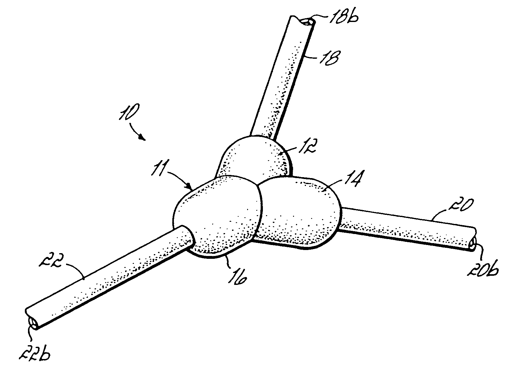
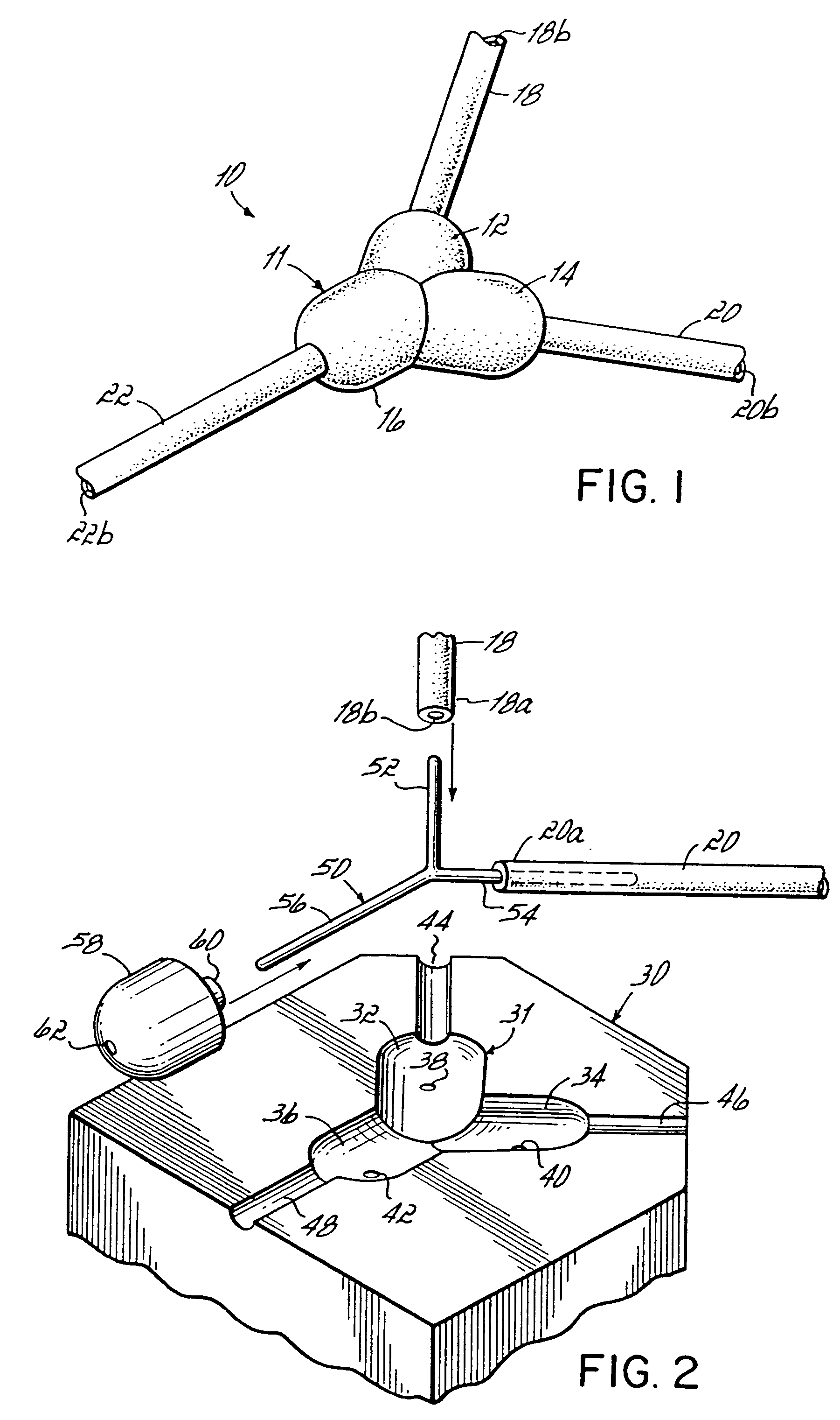
[0017]FIG. 1 illustrates a connector and tubing assembly 10 after a connector 11 has been molded with portions 12, 14, 16 holding flexible tubes 18, 20, 22 together for fluid communication therebetween. This structure therefore forms an integral fluid conveyance system which is not easily compromised at the junctions between connector 11 and tubes 18, 20, 22.

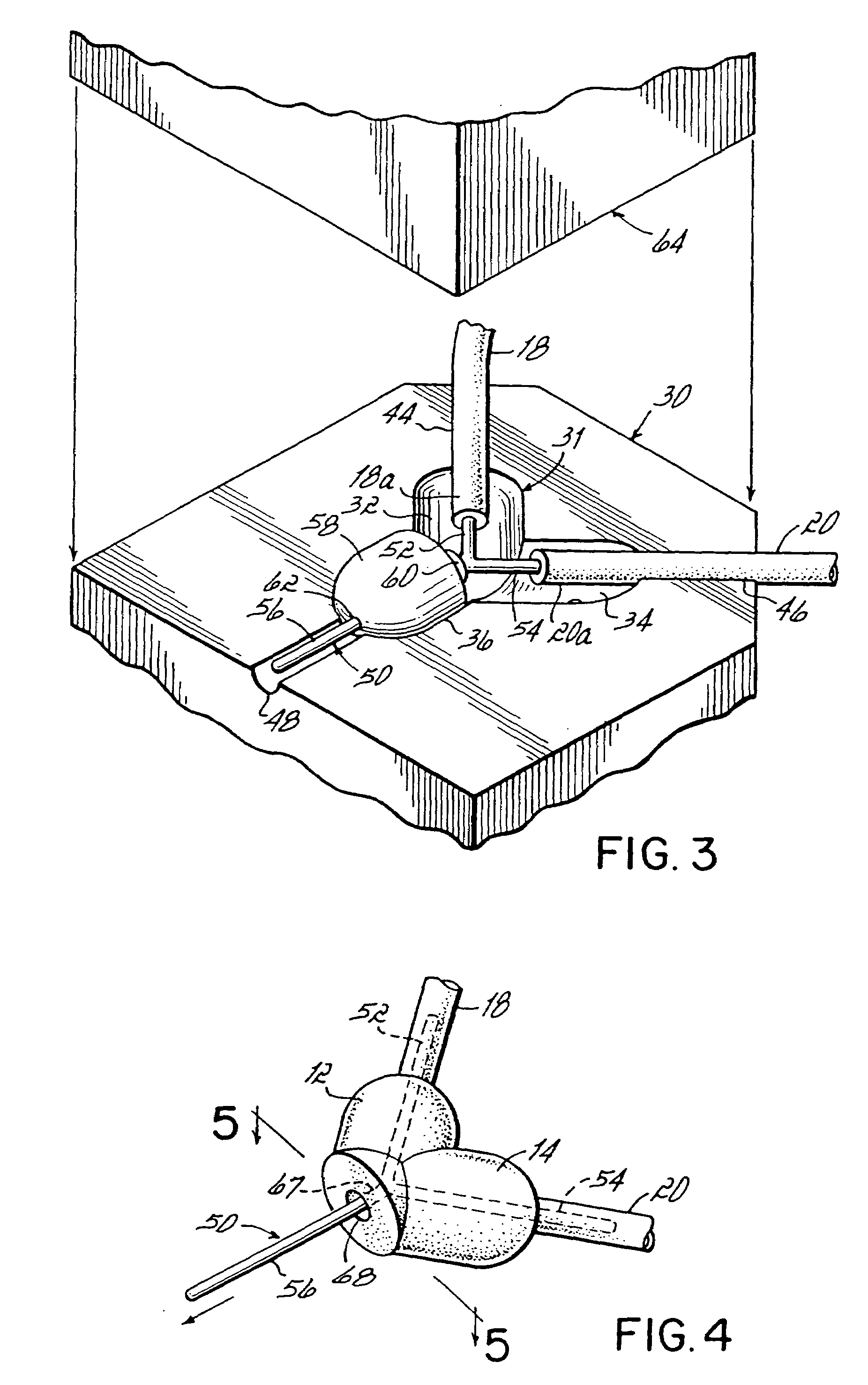
[0018]FIGS. 2–6 illustrate the preferred manner of making the connector and tubing assembly 10. First, a mold half 30 is provided having an internal mold cavity 31 in the shape of the desired connector 11. Cavity 31 is preferably formed by three smaller cavities 32, 34, 36 each having respective ports 38, 40, 42. Curable mold material, such as conventional liquid silicone, may be injected through ports 38, 40, 42 into cavity 31 after a second mold half is brought into facing engagement, as will be described below. Recesses 44, 46, 48 are respectively provided for holding tubes 18, 20, 22 such that respective connecting ends 18a,...


PUM

PropertyMeasurementUnit
flexibleaaaaaaaaaa
metallicaaaaaaaaaa
diametersaaaaaaaaaa

Abstract

A connector and tubing assembly including a multi-lumen molded connector having at least three flexible tubes also molded into the connector. The connector may be “Y” shaped and include three flexible tubes. A process of making the connector and tubing assembly involves forming a first part of the connector with two tubes molded therein and then removing an internal mold member prior to molding the final connector portion and third tube in place.

Description

[0001]This application is a continuation of application Ser. No. 09 / 951,366 (now abandoned), filed on Sep. 13, 2001 which is a divisional of application Ser. No. 08 / 909,450 filed Aug. 11, 1997 (now U.S. Pat. No. 6,290,265), the disclosures of which are fully incorporated herein by reference.FIELD OF THE INVENTION[0002]The present invention generally relates to tubing and connector assemblies and, specifically, to those assemblies utilizing multi-lumen connectors.BACKGROUND OF THE INVENTION[0003]Tubing assemblies including flexible tubing and multi-lumen connectors have been used in many applications, including those that require a high degree of assurance that contamination will not enter the system by way of the connector. Applications of such systems include closed systems in the medical field in which the flexible tubing may be clipped into a peristaltic pump used for medical purposes. Past tubing and connector assemblies have required various means for securing the connectors to...

Claims


Application Information

Patent Timeline
Patent Type & Authority Patents(United States)
IPC IPC(8): F16L47/02
CPCF16L47/02Y10T403/66A61M39/12F16L47/32A61M39/08A61M2039/087A61M2207/00A61M2207/10B29C45/14336B29C45/14467
Inventor WARBURTON-PITT, STEPHEN RONALDSTEELE, RICK ALAN
Owner SAINT GOBAIN PERFORMANCE PLASTICS CORP
Why Eureka
Try Eureka