Catheter apparatus for percutaneous coronary intervention capable of accurately positioning stent and balloon in a desired position

a catheter and stent technology, applied in the field of percutaneous coronary intervention catheter apparatus, can solve the problems of difficult to achieve the perfect positioning of the balloon and stent on the stenotic lesion of the coronary artery, difficult for even a physician with great manual skills to push forward or pull backward the balloon catheter in the artery, and difficult to achieve the perfect positioning of the balloon and stent on the stenotic lesion, so as to achieve enhanced accuracy of pci treatmen

Inactive Publication Date: 2007-11-27
SAMSUNG LIFE PUBLIC WELFARE FOUND
View PDF16 Cites 25 Cited by
  • Summary
  • Abstract
  • Description
  • Claims
  • Application Information

AI Technical Summary

Benefits of technology

[0029]The present invention provides an improved catheter apparatus for PCI capable of accurately positioning the balloon and stent at the site of an obstructive coronary artery lesion in such a convenient way that the accuracy of the PCI treatment can be enhanced and the operation time can be reduced.

Problems solved by technology

The conventional PCI treatment stated above requires that the physician must move the balloon catheter 5 very minutely on the guidewire 6, relying on the sense of his or her hands while watching the X-ray fluoroscope, in order to place the balloon 5a in the exact position of the stenotic lesion D. However, it is very difficult for even a physician having great manual skills at pushing forward or pulling backward the balloon catheter in the artery, to adjust the balloon exactly to the position of the stenotic lesion in a short time.
The accurate positioning of the balloon and stent depends on the physician's hands and is not an easy task.
However, even if the physician pays much attention to his or her manual movements, it is usually difficult to attain perfect positioning of the balloon and stent on a stenotic lesion of the coronary artery.
In PCI treatment using the conventional catheter apparatus, since the physician has to make small changes to the position of the balloon catheter by depending on his or her manual dexterity, it is very difficult to install the stent exactly at the position of the stenotic lesion (especially, at a curved or tortuous lesion) due to an excessive movement of the balloon and stent in the arteries.
This may result in the installation of the stent in a less than optimal position, thereby causing less than ideal results.
In addition, it takes much time to perform PCI treatment using the conventional catheter apparatus.
Accordingly, the patient has to experience much pain due to the extended time of the operation, thereby adversely affecting the patient's prognosis.

Method used


Image

  • Catheter apparatus for percutaneous coronary intervention capable of accurately positioning stent and balloon in a desired position
  • Catheter apparatus for percutaneous coronary intervention capable of accurately positioning stent and balloon in a desired position
  • Catheter apparatus for percutaneous coronary intervention capable of accurately positioning stent and balloon in a desired position

Examples


first embodiment

[0043]FIG. 3 shows a catheter apparatus for PCI according to the present invention. FIG. 4 is a side view of the catheter apparatus of FIG. 3, and FIG. 5 is a longitudinal cross-sectional view of the catheter apparatus of FIG. 3.

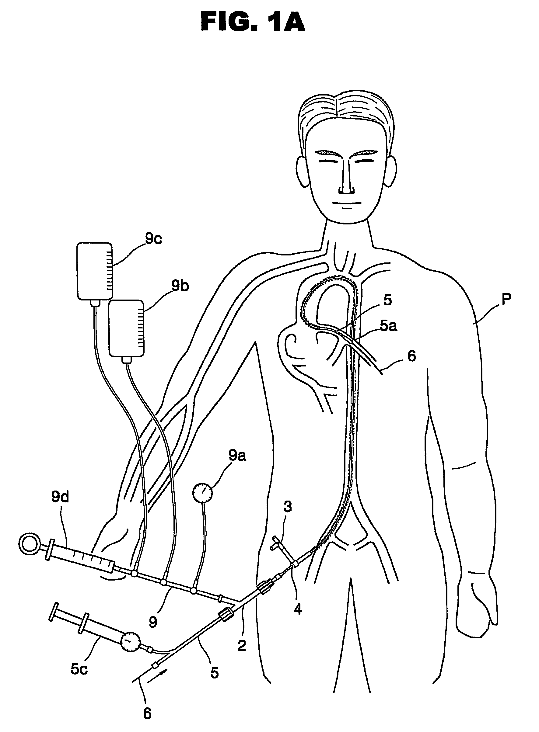
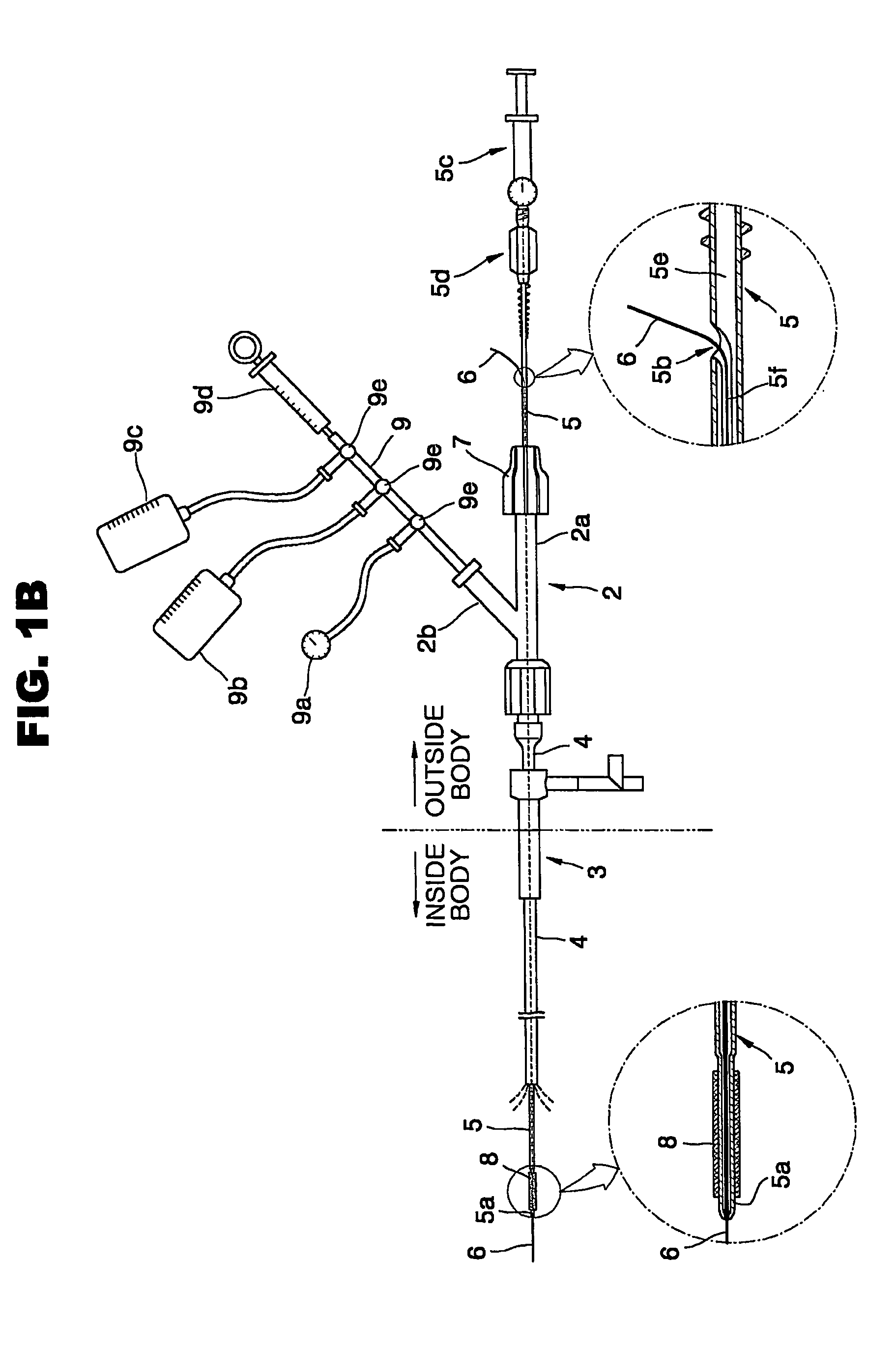
[0044]Referring to FIGS. 3, 4 and 5, a Y-connector 110, an introducer set 130, a guiding catheter 140, a balloon catheter 150, a guidewire 160 and a stent 180 are the same as those shown in FIGS. 1B and 1C. Therefore, a detailed description of those components will be omitted.

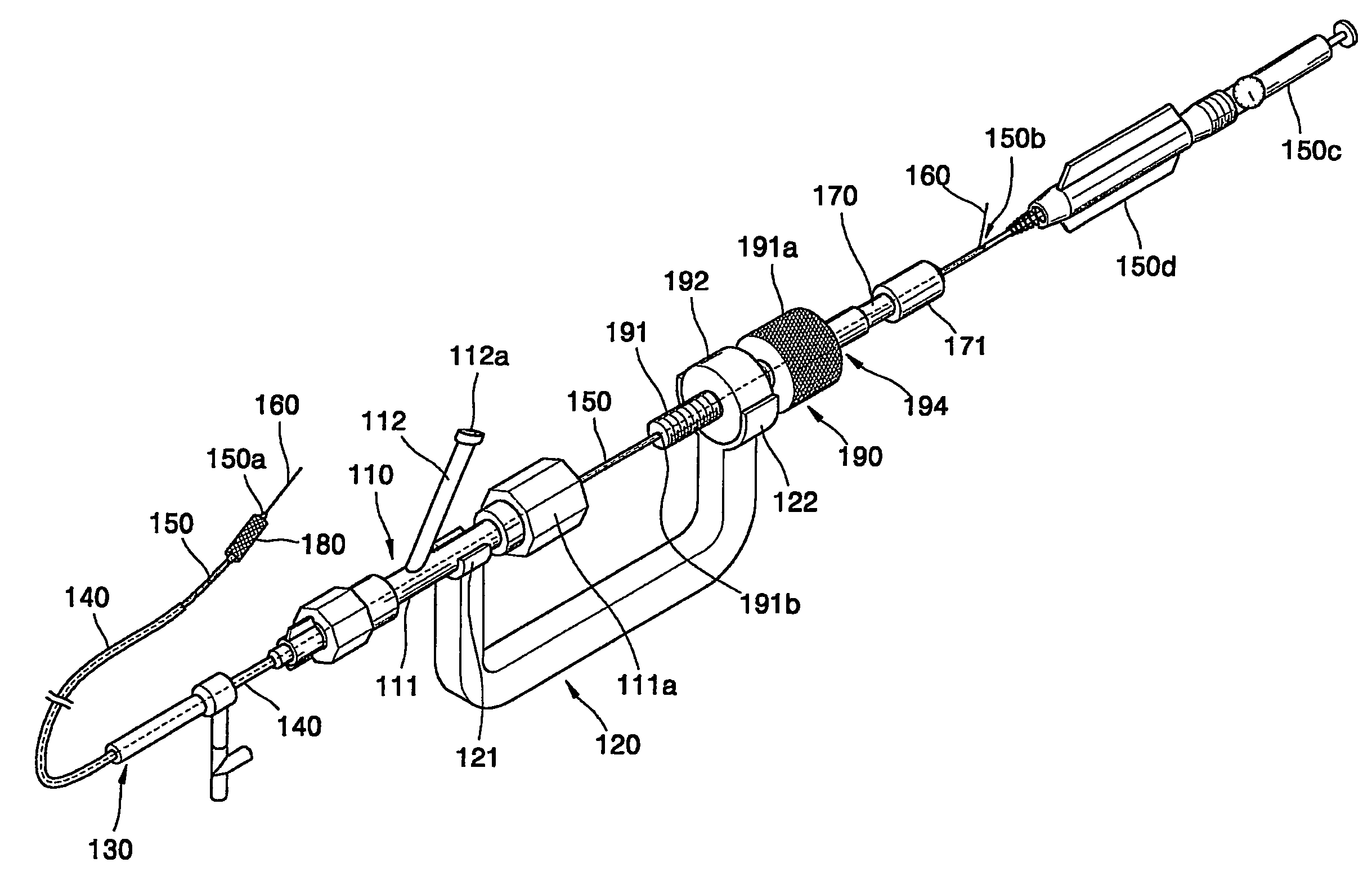
[0045]The catheter apparatus 100 for PCI according to the present invention includes a U-shaped combining frame 120 with clips 121 and 122 formed at the respective ends thereof. The first clip 121 can be coupled with a circumferential surface of a main tube 111, and can be separated from the main tube 111 by pulling the first clip 121 from the circumferential surface of the main tube 111. Moreover, the second clip 122 formed at the other end of the combining frame 120 can be coupled wit...

second embodiment

[0057]FIG. 6 shows a catheter apparatus for PCI according to the present invention. FIG. 7 is an illustration of the catheter apparatus of FIG. 6, with certain parts of the apparatus disassembled, and FIG. 8 is a perspective view of the catheter apparatus of FIG. 7, excluding the minute adjustment nut 193. FIG. 9A is a detailed view of the Y-connector 110 and the minute adjustment nut 193 of the apparatus shown in FIG. 6, and FIG. 9B shows the combination of a first bolt 195 and a second bolt 196.

[0058]The catheter apparatus for PCI according to the second embodiment of the present invention differs from that of the first embodiment stated above, in that the mechanism for minutely adjusting the insertion position of the balloon catheter in the artery comprises a first bolt 195, a second bolt 196 and a minute adjustment nut 193.

[0059]The first bolt 195 is integrated with the main tube 111 of the Y-connector 110, and it has a first screw portion 195a on its circumferential surface. Th...


PUM


Abstract

A catheter apparatus for percutaneous coronary intervention (PCI) capable of accurately positioning the balloon and stent in a desired position includes an introducer set fixed to an opening of the human artery, a guiding catheter secured to the introducer set and introduced into the artery, a Y-connector coupled with the guiding catheter, a guidewire introduced into the guiding catheter, a balloon catheter introduced into the guiding catheter and having a balloon at the distal end thereof, a minute adjustment portion having a nut and a bolt for minutely adjusting the insertion portion of the balloon catheter in the artery, a combining frame having two legs eachcoupled with the main tube and the nut, respectively, and a clamping portion for holding the balloon catheter firmly in position. The catheter apparatus provided by the present invention helps the physician to place the balloon and stent more accurately in the desired position of the artery so that the PCI operation becomes more accurate, easier and safer.

Description

[0001]This application is a 371 ofPCT / KR2003 / 001321 filed on Jul. 4, 2003, published on Mar. 18, 2004 under publication number WO 2004 / 021930 A1 which claims priority benefits from Korean patent application number KR 10-2002-0054323 filed Sep. 9, 2002.BACKGROUND OF THE INVENTION[0002]1. Field of the Invention[0003]The present invention relates to an improved catheter apparatus for percutaneous coronary intervention (PCI), and more particularly to a catheter apparatus for PCI whereby a balloon catheter can be moved more accurately to place a balloon formed at the distal end of the balloon catheter and a stent mounted on the balloon in a position of a human coronary artery having a cardiovascular disease such as a stenotic lesion.[0004]2. Description of the Related Art[0005]Coronary arteries of a human blood circulation system are tubes that supply the heart with oxygen, blood and nutritive substances. The left and right coronary arteries branching off from the ascending aorta spread ...

Claims


Application Information

Patent Timeline
Patent Type & Authority Patents(United States)
IPC IPC(8): A61F2/06A61F2/95A61F2/958
CPCA61F2/95A61F2/958A61F2002/9517A61F2/9517A61F2/07A61F2/86A61M25/00
Inventor PARK, JEONG EUYKWON, HYUK NAM
Owner SAMSUNG LIFE PUBLIC WELFARE FOUND
Why Eureka
Try Eureka