Connector

a technology of connecting rods and locking rods, applied in the direction of connection, electrical apparatus, coupling device connection, etc., can solve the problem of insufficient strength of locking rods, and achieve the effect of reducing the overall height of the connector and stable holding for

Active Publication Date: 2006-08-22
DDK LTD
View PDF11 Cites 42 Cited by
  • Summary
  • Abstract
  • Description
  • Claims
  • Application Information

AI Technical Summary

Benefits of technology

[0020]It is an object of the invention to provide an improved connector which overcomes all the disadvantages of the prior art and which ensures a stable holding force for a flexible printed circuit board even with less contacts without causing defective or failed connection and achieves further reduced overall height of the connector.
[0028]As can be seen from the above description, the connector 10 according to the invention brings about the following significant effects.
[0029](1) In a connector 10 detachably fitted with a flexible printed circuit board 80, including a plurality of contacts 14 each having a contact portion 64 to contact the flexible printed circuit board 80, a housing 12 holding and fixing the contacts 14 and having a fitting opening 40 into which the flexible printed circuit board 80 is inserted, locking members 18 adapted to engage the flexible printed circuit board 80, and a pivoting member 16 causing the contacts 14 and the locking members 18 to be elastically deformed, according to the invention, the flexible printed circuit board 80 is provided with anchoring portions 82, and the locking members 18 each comprise a first piece 20 having an engaging portion 24 at one end adapted to engage the anchoring portion 82 of the flexible printed circuit board, a pressure receiving portion 26 at the other end adapted to be urged by the pivoting member 16, and a projection 34 inwardly extending from the tip of the pressure receiving portion 26; a second piece 22 having a connection portion 30 at one end or the other end to be connected to a substrate; and a jointing fulcrum portion 32 for connecting the first piece 20 and the other end or the one end of the second piece 22; the locking members 18 being installed on the housing 12, and further the housing 12 is provided with notches 42 on the side of its upper surface at positions corresponding to the locking members 18. Therefore, a simple construction of the locking members 18 ensures sufficient displacements of the engaging portions 24 of the locking members 18 and can reduce the overall height by about 0.13 to 0.17 mm.
[0030](2) In a connector 10 detachably fitted with a flexible printed circuit board 80, including a plurality of contacts 14 each having a contact portion 64 to contact the flexible printed circuit board 80, a housing 12 holding and fixing the contacts 14 and having a fitting opening 40 into which the flexible printed circuit board 80 is inserted, locking members 18 adapted to engage the flexible printed circuit board 80, and a pivoting member 16 causing the contacts 14 and the locking members 18 to be elastically deformed, according to the invention the flexible printed circuit board 80 is provided with anchoring portions 82, and the locking members 18 each comprise a first piece 20 having an engaging portion 24 at one end adapted to engage the anchoring portion 82 of the flexible printed circuit board, a pressure receiving portion 26 at the other end adapted to be urged by the pivoting member 16, and a projection 34 inwardly extending from the tip of the pressure receiving portion 26; a second piece 22 having a connection portion 30 at one end to be connected to a substrate; and a jointing fulcrum portion 32 for connecting the first piece 20 and the other end of the second piece 22; the locking members 18 being installed on the housing 12, and further the second pieces are void of parts at positions facing to the engaging portions 24 of the first piece when the pivoting member 16 is pivotally moved to bring the engaging portions 24 of the locking members 18 into engagement with the anchoring portions 82 of the flexible printed circuit board 80. Accordingly, a simple construction of the locking members 18 ensures sufficient displacements of the engaging portions 24 of the locking members 18, and the connector 10 according to the invention can achieve a stable holding force fully complying with customer's requirements for a flexible printed circuit board and hence provide stable connection.
[0032](4) According to the invention, the second pieces 22 each include an extension portion 28 extending from the jointing fulcrum portion 32 in such a direction that the extension portion faces to the engaging portion 24, and the length of the extension portion 28 is shorter than the distance from the jointing fulcrum portion to the engaging portion 24 so that the extension portions 28 stop short of the positions facing to the engaging portions 24 when the pivoting member 16 is pivotally moved to bring the engaging portions 24 of the locking members 18 into engagement with the anchoring portions 82 of the flexible printed circuit board 80. Therefore, as there are provided the notches 42 in the upper surface of the housing 12, a simple construction of the locking members 18 ensures sufficient displacements of the engaging portions 24 of the locking members 18, and the connector according to the invention can achieve a stable holding force fully complying with customer's requirements for a flexible printed circuit board and hence provide stable connection and further can reduce the overall height of the connector by approximately 0.2 mm.
[0034](6) According to the invention, the contacts 14 each comprise a first piece 60 having a contact portion 64 at one end adapted to contact the flexible printed circuit board 80, a pressure receiving portion 66 at the other end adapted to be urged by the pivoting member 16, and a projection 74 inwardly extending from the tip of the pressure receiving portion 66; a second piece 62 having a connection portion 70 at one end to be connected to a substrate and at the other end an extension portion 68 extending from a fulcrum portion 72; and a jointing portion 73 for connecting the first piece 60 and the fulcrum portion 72 of the second piece 62; the contact portion 64, the jointing portion 73, the fulcrum portion 72, and the connection portion 70 are arranged substantially in the form of a U-shape, and further the pivoting member 16 comprises an actuating portion 44 for pivotally moving the pivoting member, urging portions 46 arranged continuously in the longitudinal direction, and anchoring holes 48 into which the pressure receiving portions 66 and 26 of the contacts 14 and the locking members 18 can be inserted, and the pivoting member 16 is installed on the housing 12 so that the urging portions 46 are pivotally moved between the pressure receiving portions 66 and the extension portions 68 of the contacts 14 and between the pressure receiving portions 26 and the connection portions 30 of the locking members 18. Accordingly, it is possible to provide a connector 10 which requires no force for inserting a flexible printed circuit board 80 with the aid of the simple construction of the contacts 14 similar to the locking members 18.

Problems solved by technology

On the other hand, if it is less than 0.08 mm, the strength of the locking members may become insufficient.

Method used


Image

  • Connector
  • Connector
  • Connector

Examples


Embodiment Construction

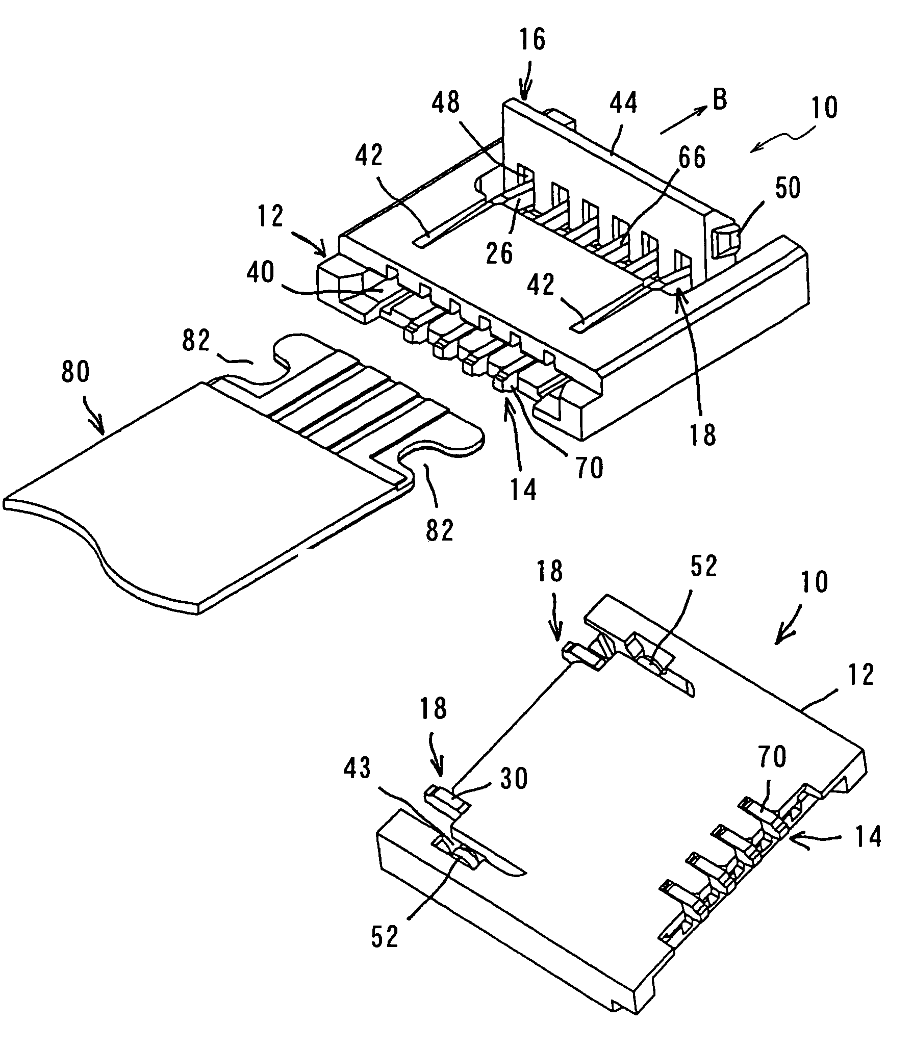
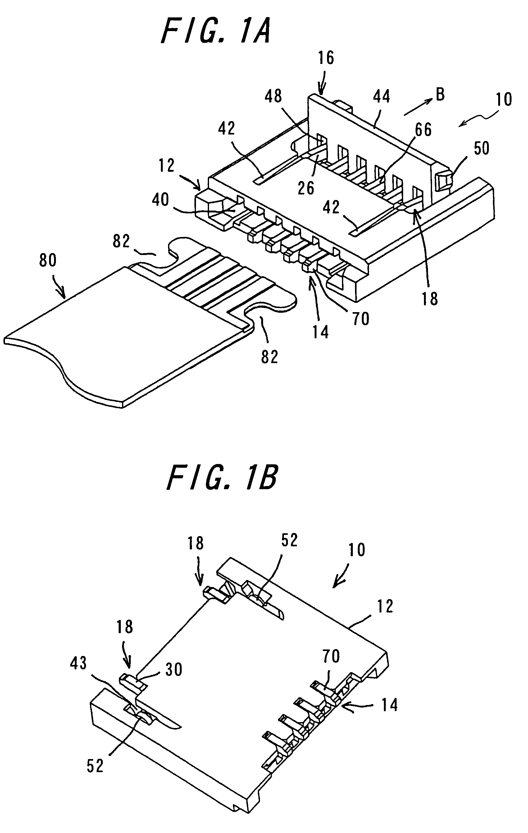
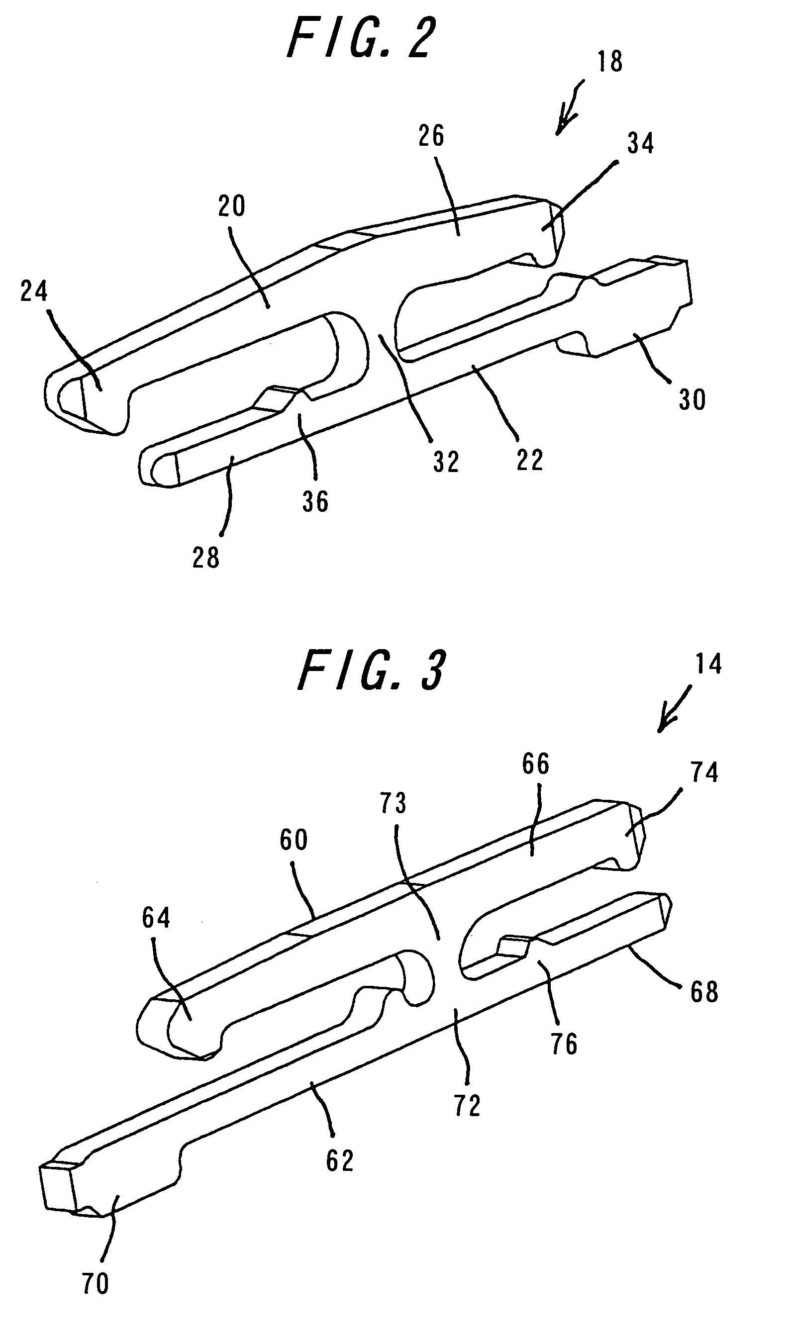
[0045]One embodiment of the connector according to the invention will be explained with reference to FIGS. 1A to 6B. FIG. 1A is a perspective view of the connector according to the invention and a flexible printed circuit board which is partly removed and has not been inserted into the connector, viewed from the above on the fitting opening side. FIG. 1B is a perspective view of the connector shown in FIG. 1A into which the flexible printed circuit board has not been inserted, viewed from the below on the fitting opening side. FIGS. 2 to 4 are perspective views of a locking member, a contact and a pivoting member used in the connector according to the invention, respectively. FIG. 5A is a sectional view of the connector not having a flexible printed circuit board inserted, taken along one locking member. FIG. 5B is a sectional view of the connector with the inserted flexible printed circuit board, taken along one locking member. FIG. 6A is a sectional view of the connector not havin...


PUM


Abstract

Locking members installed in a housing of a connector each include a first piece having at one end an engaging portion to engage the anchoring portion formed in a flexible printed circuit board, a pressure receiving portion at the other end to be urged by a pivoting member, and a projection inwardly extending from the pressure receiving portion; a second piece having at one end a connection portion connected to a substrate; and a jointing fulcrum portion connecting the first and second pieces. When the engaging portions of the locking members engage the anchoring portions of the circuit board, the second pieces are void of parts facing to the engaging portions. The housing includes notches at positions corresponding to the locking members. The connector achieves further reduced overall height and stable holding force for the circuit board even with less conductors without failed connection.

Description

CROSS-REFERENCE TO RELATED APPLICATIONS[0001]This application claims priority from Japanese Patent Application No. 2004-334,060, filed Nov. 18, 2004, which is incorporated by reference in its entirety.BACKGROUND OF THE INVENTION[0002]The present invention relates to a connector for use in mobiles, backlight liquid crystal displays and the like, and more particularly to a connector capable of reliably locking a flexible printed circuit board to the connector when the circuit board has been inserted thereinto.[0003]In general, connectors for use in mobile phones, charge coupled device (CCD) cameras and the like are much thinner and having contacts arranged in extremely narrow pitches (so-called lighter and more compact connector). A connector of one type mainly comprises a housing and contacts, and a flexible printed circuit board is inserted into the housing to bring the circuit board into contact with contact portions of the contacts (so-called “non-zero-insertion force (NZIF)” type...

Claims


Application Information

Patent Timeline
Patent Type & Authority Patents(United States)
IPC IPC(8): H01R12/24
CPCH01R12/771H01R12/88H01R12/79
Inventor NAKANO, YUKISUZUKI, MASAYUKI
Owner DDK LTD
Why Eureka
Try Eureka