Method for control of washcoat distribution along channels of a particulate filter substrate

a technology of filter substrate and washcoat, which is applied in the direction of physical/chemical process catalyst, separation process, metal/metal-oxide/metal-hydroxide catalyst, etc., can solve the problems of increased flow restriction, increased exhaust line backpressure, and detrimental to engine performance and fuel economy

Active Publication Date: 2006-08-22
UMICORE AG & CO KG
View PDF11 Cites 59 Cited by
  • Summary
  • Abstract
  • Description
  • Claims
  • Application Information

AI Technical Summary

Benefits of technology

[0004]In another aspect, a method of distributing a washcoat along channels of a particulate filter substrate includes: forcing a slurry traveling a predetermined distance in the channels of DPF substrate; applying a first vacuum to a first end of the particulate filter substrate to clear an excess amount washcoat slurry from the channels; and applying a second vacuum to a second end of the particulate filter substrate to arrange a remainder of t...

Problems solved by technology

However, an increase in washcoat loading can result in an increase in flow restriction when exhaust gas flows by the catalytic particulate filter.
This i...

Method used


Image

  • Method for control of washcoat distribution along channels of a particulate filter substrate
  • Method for control of washcoat distribution along channels of a particulate filter substrate
  • Method for control of washcoat distribution along channels of a particulate filter substrate

Examples


example 1

Sample A—A Particulate Filter Substrate Having an Evenly Coated Washcoat Throughout the Inlet Channels

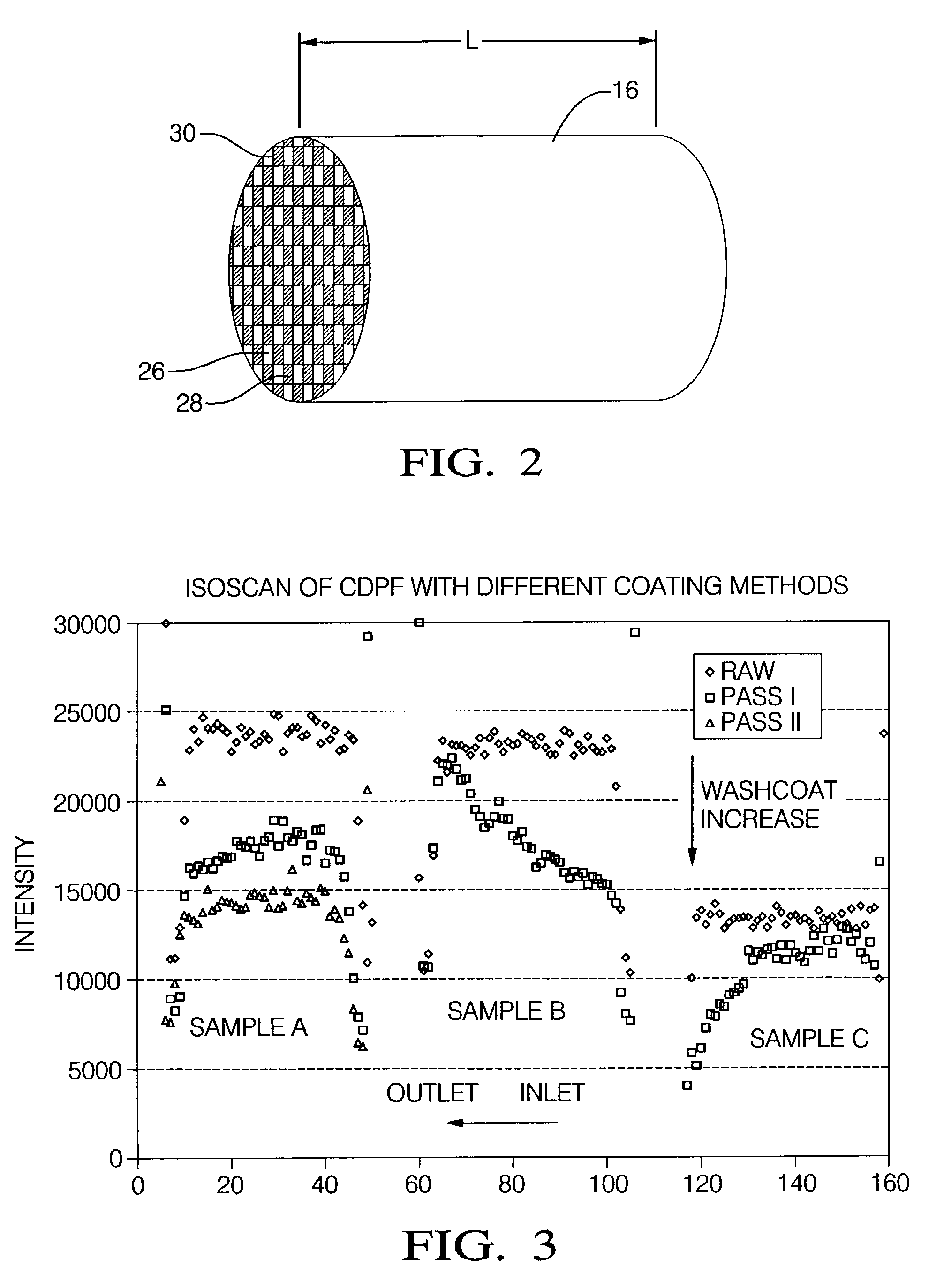
[0022]To evenly load washcoat throughout the inlet channels of the particulate filter substrate, an amount of washcoat slurry and its solid content is selected to allow an even number of applications, with each application having slurry fully forced into the inlet channels of the particulate filter (100% of L). In the first application, the washcoat slurry is fully forced into the inlet channels via the inlet end of the filter substrate. A first clearing is then accomplished by applying a vacuum to the outlet end of the filter substrate such that the vacuum draws the washcoat slurry in the same direction that it was forced into to the particulate filter substrate. Next, the particulate filter substrate is flipped and the vacuum is applied to the inlet end to draw the excess washcoat slurry in an opposite direction, toward the inlet end. An isoscan of a particulate filter substrate i...

example 2

Sample B—Washcoat Loading Biased Towards the Inlet End of the Inlet Channels

[0023]Loading more washcoat at the inlet end of the inlet channels can be achieved by forcing slurry only partially into the inlet channels of the particulate filter substrate (e.g., 50% of L), followed by application of vacuum to the inlet end. The washcoat gradient (i.e., arrangement of catalytically active material) is generated with higher washcoat loading toward the inlet end. Sample B in FIG. 2 demonstrates a particulate filter substrate having a coating formed by this process using a 50% slurry filling (50% of L). As can be seen in FIG. 2 at Sample B, there is almost no washcoat near the outlet end of the particulate filter substrate.

example 3

Sample C—Washcoat Loading Biased Towards the Outlet End of the Inlet Channels of the Particulate Filter Substrate

[0024]Loading more washcoat toward the outlet end of the inlet channels can be achieved by using one-pass application and 100% slurry fill (100% of L). In the application, the washcoat slurry is fully forced into the inlet channels via the inlet end of the filter substrate. A vacuum is then applied to the outlet end of the filter substrate, followed by applying vacuum to the inlet end, causing the slurry to move towards the outlet end. Sample C in FIG. 2 demonstrates a particulate filter substrate having a coating formed by this process. As can be seen in FIG. 2 at Sample C, there is almost no washcoat near the inlet end of the particulate filter substrate.


PUM

PropertyMeasurementUnit
Lengthaaaaaaaaaa
Timeaaaaaaaaaa
Distanceaaaaaaaaaa

Abstract

Disclosed herein is a method of distributing a washcoat along channels of a particulate filter substrate, the method including: forcing a washcoat slurry a predetermined distance into the channels, the predetermined distance being less than or equal to the full length of the channels; clearing an excess amount of washcoat slurry from the channels; and arranging a remainder of the washcoat slurry within the channels, the arranging including applying a first vacuum to a first end of the particulate filter substrate after the clearing. In one embodiment the clearing includes applying a second vacuum to a second end of the particulate filter substrate. In another embodiment, the clearing includes pulling the excess washcoat slurry from the channels. The predetermined distance may be less than or equal to the full length of the channels. The arranging may provide a layer of a washcoat composition comprising a catalytically active material arranged anisotropically along a length of the channels of the particulate filter substrate.

Description

BACKGROUND[0001]Federal and state requirements have mandated substantial reductions in carbon particulate matter (PM, so called soot), hydrocarbons, nitrogen oxides and carbon monoxide emission for gasoline and diesel engines. Attempts at reducing such emissions, in particular attempts to reduce particulate emissions from diesel engines, include catalytic diesel particulate filters (DPF) in which a catalytically active material is dispersed within a substrate in the particulate filter. The catalyst promotes removal (e.g., oxidation) of particulates and other pollutants of diesel fuel combustion in the exhaust gas stream.[0002]Applying a catalytic material (also referred to herein as a washcoat) to the DPF substrate is one of the most promising technologies for effective removal (combustion) of trapped PM. In general, better catalytic performance is achieved by increasing washcoat loading so as to increase the concentration of catalytically active material present. However, an increa...

Claims


Application Information

Patent Timeline
IPC IPC(8): B01J37/02B01D46/24B01D53/94B01J23/00B01J23/02B01J23/10B01J23/16B01J23/40B01J35/00F01N3/022
CPCB01D46/2422B01D46/4218B01D53/94B01J35/0006B01J37/0215F01N3/0222B01D2255/9202B01J23/02B01J23/10Y10S502/514B01J23/40F01N2330/06Y02T10/20B01J23/16Y02T10/12
Inventor YAN, JIYANGREID, SCOTT F.WEI, MING
Owner UMICORE AG & CO KG
Why Eureka
Try Eureka