Frequency-selective shield structure and electric device having the structure

a shield structure and frequency-selective technology, applied in the direction of electrical apparatus construction details, line-transmission details, instruments, etc., can solve the problems of low selectivity of antennas, radio interference between radio communication interfaces and radio wave emission to the outside, and easy to affect the radio communication interface by external electromagnetic noise, etc., to prevent radio interference, simple structure, and high frequency selectivity

Active Publication Date: 2006-08-22
MAXELL HLDG LTD
View PDF9 Cites 13 Cited by
  • Summary
  • Abstract
  • Description
  • Claims
  • Application Information

AI Technical Summary

Problems solved by technology

However, the radio communication interface is easily affected by external electromagnetic noise.
In addition, there is a problem of radio interference between radio communication interfaces and emission of a radio wave to the outside.
However, this technique has a problem that the frequency selectivity of the antenna is low and the emission of the radio wave is significant in a frequency band higher than the radiant frequency of the antenna.
Therefore, the structure for mounting the antenna portion on the shield plate becomes complicated, and the thickness of the shield plate increases, resulting in a complicated manufacturing process.
This results in a problem that the antenna is broken by falling of the device or a shock caused by touch.
In the case where a notch is provided in the shield structure, there is a problem that the notch cannot be made large to minimize the EMI and the directivity of the antenna becomes narrow, or a problem that the antenna gain cannot be made sufficiently large.

Method used


Image

  • Frequency-selective shield structure and electric device having the structure
  • Frequency-selective shield structure and electric device having the structure
  • Frequency-selective shield structure and electric device having the structure

Examples


Embodiment Construction

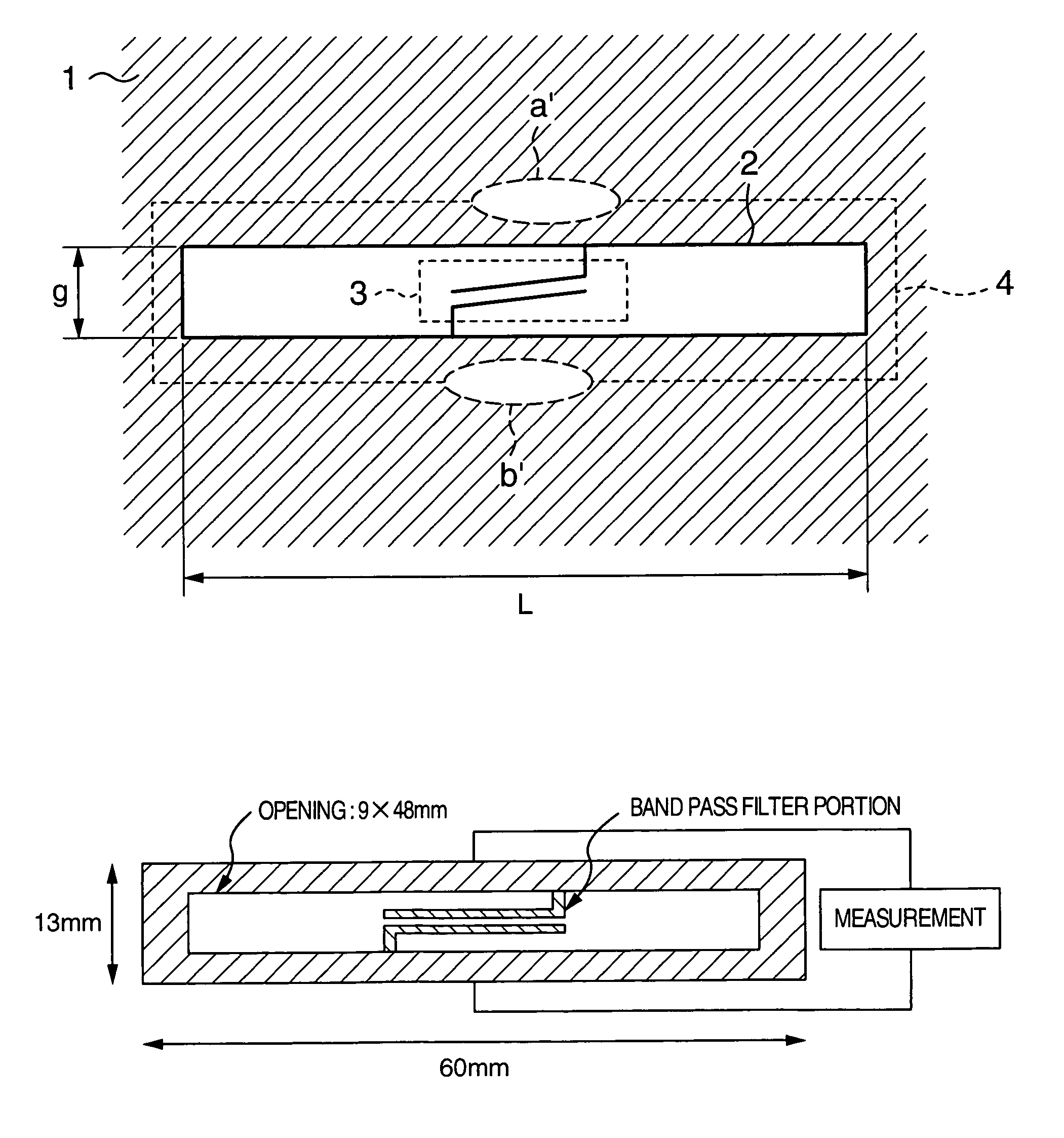
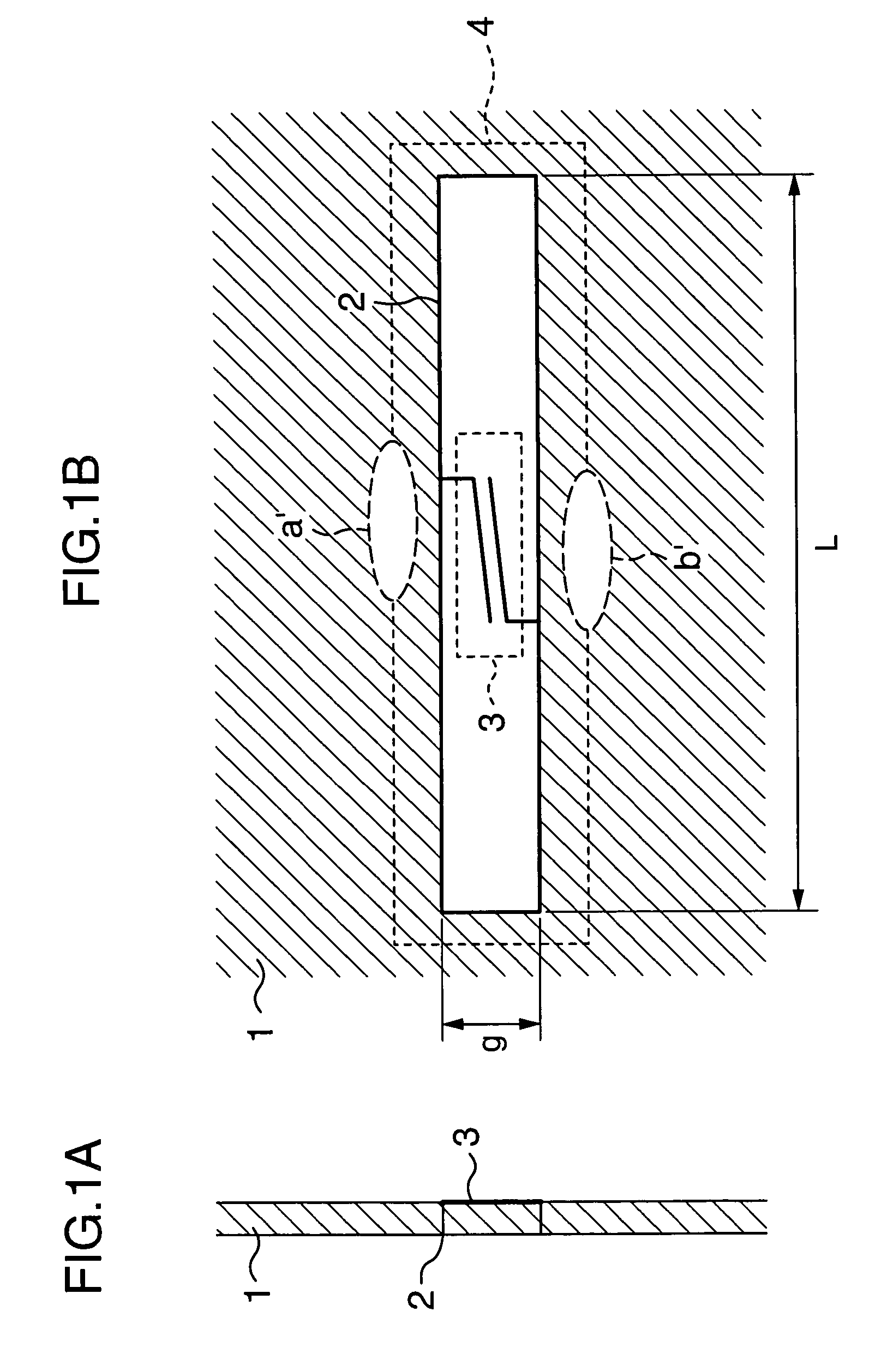
[0024]FIGS. 1A and 1B show how a frequency-selective shield structure is formed in a conductor having a size that is large enough to intercept radio waves.

[0025]FIG. 1A is a sectional view of a conductor 1 having a frequency-selective shield structure formed therein. As shown in FIG. 1A, an opening portion 2 having a perimeter length that substantially coincides with a wavelength of a radio wave having a frequency to be transmitted is provided in the conductor 1. This opening portion passes through both surfaces of the conductor. The opening portion 2 functions as a slot antenna for a radio wave having a frequency that can be transmitted according to the perimeter length. Denoting a length of a short side of the opening portion 2 by “g” and a length of a long side of the opening portion 2 by “L,” the length of the perimeter=2(g+L).

[0026]In addition, a high frequency filter 3 is formed on one surface of the conductor. The high frequency filter 3 may be formed on either of the surface...


PUM


Abstract

A shield structure that transmits a radio wave in a specific frequency band and that exhibits a high shield characteristic in other bands. An opening portion having a specific shape and a specific perimeter length is formed on a conductor. A filter having a specific shape and a specific size is connected to the opening portion.

Description

BACKGROUND OF THE INVENTION[0001]The present invention relates to a technique for selectively transmitting a radio wave having a predetermined frequency.[0002]In recent years, the radio communication interface has spread in personal computers. A portable information device such as a notebook computer is carried freely and connected to a LAN environment into which the portable information device has been carried, by radio to conduct work. Such a use form has become widespread. However, the radio communication interface is easily affected by external electromagnetic noise. In addition, there is a problem of radio interference between radio communication interfaces and emission of a radio wave to the outside. Therefore, radio interference from external electromagnetic noise and emission of a radio wave are prevented by using a shield plate for shielding the radio wave.[0003]If the shield plate is installed, however, the space is bisected via the shield plate to a region where a radio w...

Claims


Application Information

Patent Timeline
Patent Type & Authority Patents(United States)
IPC IPC(8): H05K9/00H04B3/21G06F1/16H01Q13/10H01Q15/22H01Q17/00
CPCH05K9/0003
Inventor YOKOTA, HITOSHI
Owner MAXELL HLDG LTD
Why Eureka
Try Eureka