Trolley structure

a technology of trolleys and trolleys, applied in the direction of trolleys/perambulators with multiple axes, folding cycles, cycles, etc., can solve the problems of excessively large stand area (c) consuming too much space, teeth could easily break down and fail to turn,

Active Publication Date: 2006-08-29
BEST CADDY
View PDF15 Cites 43 Cited by
  • Summary
  • Abstract
  • Description
  • Claims
  • Application Information

AI Technical Summary

Benefits of technology

[0009]2. Whereas a plurality of troughs are provided at the bottom of the wheel base and a fan-shaped member is provided to one side of the driven gear, ...

Problems solved by technology

Usually a conventional trolley is provided with a fixed stand, which is not easy to carry and consumes too much space.
As a result the excessively large area of the stand (C) consumes too much space.
Fu...

Method used


Image

  • Trolley structure
  • Trolley structure
  • Trolley structure

Examples


Embodiment Construction

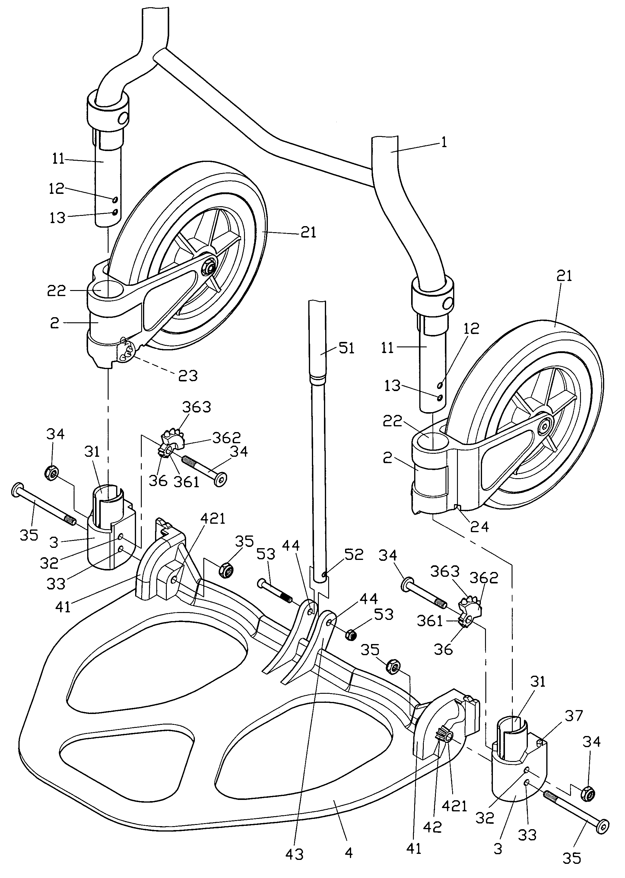
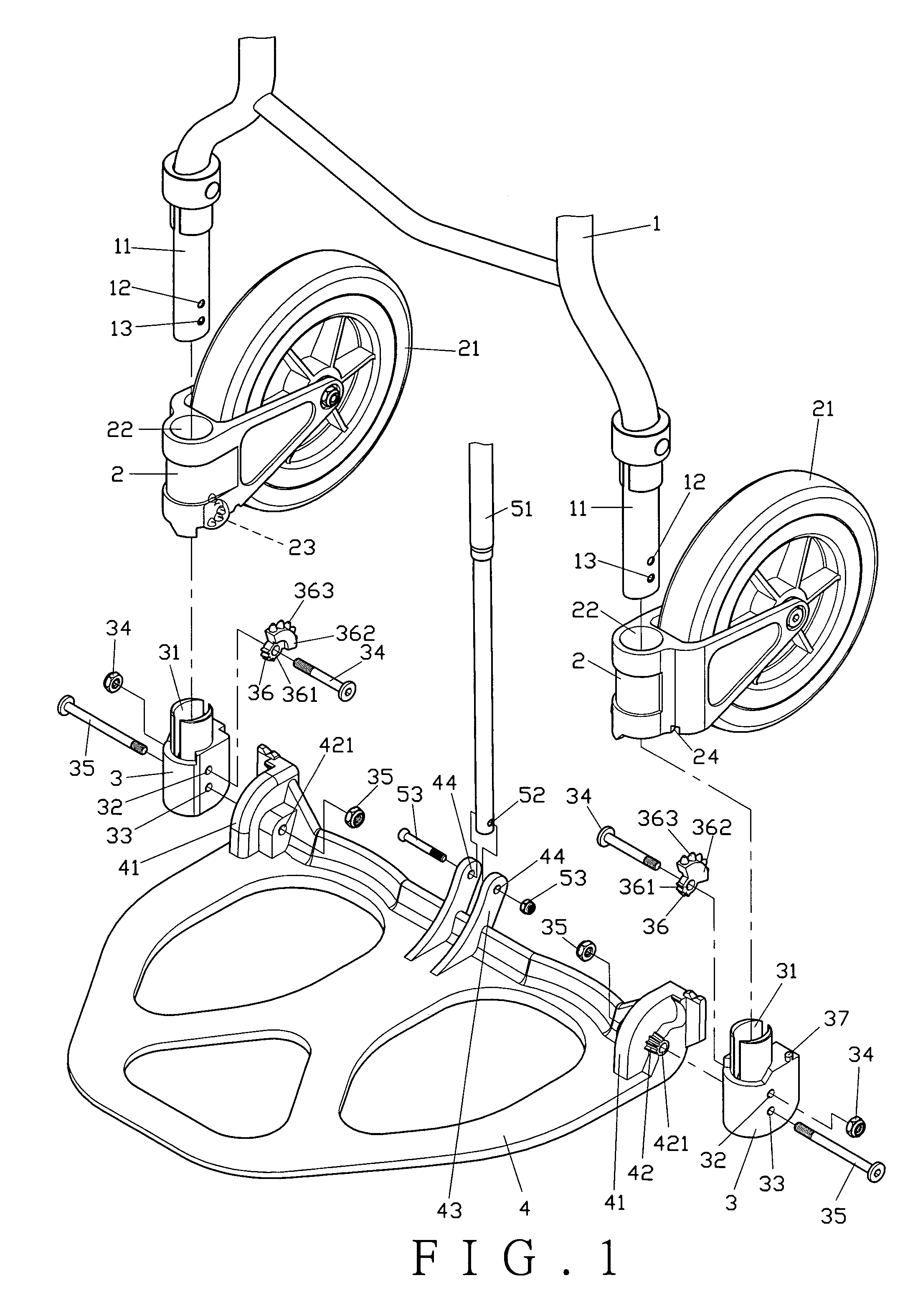
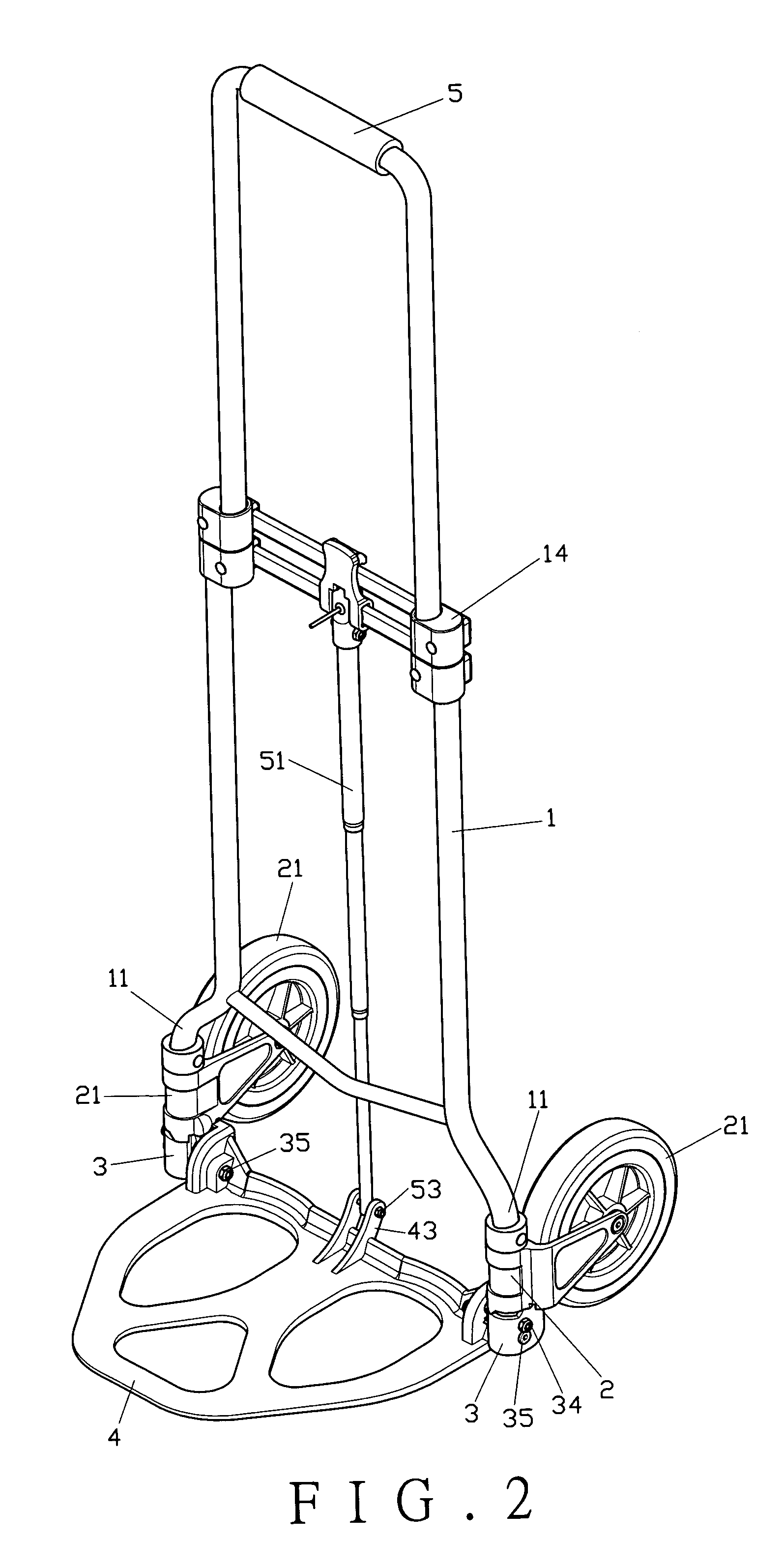
[0018]Referring to FIGS. 1 and 2, a preferred embodiment of the present invention comprises a main frame (1), wheel bases (2), retainers (3), a stand (4), and a handlebar (5).

[0019]The main frame (1) is at its bottom on respective sides provided with a rod (11). Each rod (11) is provided with a first through hole (12) and a second through hole (13). A retractable holder (14) is each provided at respective top ends of the main frame (1).

[0020]Each wheel base (2) inserted onto the respective rod (11) of the main frame (1) is provided with a wheel (21) and an opening (22), while a plurality of troughs (23) and a chute (24) are provided at the bottom of each wheel base (2).

[0021]Each retainer (3) secured to the respective rod (11) of the main frame (1) is provided with an opening (31), a first through hole (32) and a second through hole (33) to respectively receive insertion of a first pivoting member (34) and a second pivoting member (35). A driven gear (36) is pivoted to the first piv...


PUM


Abstract

A trolley structure allowing synchronous retraction or extension of a stand and two wheels includes a main frame, wheel bases, retainers, a stand, and a handlebar; each wheel base inserted onto a respective rod of the main frame and fixed with the respective retainer; the stand pivoted to the retainers; the handlebar inserted into retractable holders of the main frame; a plurality of troughs provided at the bottom of each wheel base; a driven gear pivoted to the outer edge of each retainer; a plurality of checking members provided on the driven gear to be held in the troughs for driving the driven gear to rotate; and an active gear provided on a first pivoting holder of the stand to mesh with the driven gear to drive the driven gear to turn.

Description

BACKGROUND OF THE INVENTION[0001](a) Field of the Invention[0002]The present invention relates to a trolley structure, and more particularly, to one that allows reliable transmission and reduced stand area for savings in production cost and space consumed.[0003](b) Description of the Prior Art[0004]Usually a conventional trolley is provided with a fixed stand, which is not easy to carry and consumes too much space. Therefore, an improved structure is therefore introduced, which is retractable as illustrated in FIG. 7 of the accompanying drawings. The trolley comprises a main frame (A) and a retractable handlebar (B). The main frame (A) comprises a pair of rods (A1) at respective bottom ends of the main frame (A). A rotary wheel frame (A2) is inserted onto each rod (A1) to hold a wheel (A3). A gear (A4) is provided on the quarter of the outer circumference at the bottom of each wheel frame (A2) as illustrated in FIG. 8. A stand (C) is pivoted to the bottom of each rod (A1) and is con...

Claims


Application Information

Patent Timeline
IPC IPC(8): B62B1/12
CPCB62B1/12B62B2205/30B62B2205/12B62B2205/003B62B2205/18
Inventor SU, CHUNG-SHIU
Owner BEST CADDY
Why Eureka
Try Eureka