Positioning structure of a beach umbrella

a technology of positioning structure and umbrella, which is applied in the direction of umbrellas, rod connections, manufacturing tools, etc., can solve the problems of difficult to insert the shaft of the umbrella into the ground in a stable manner

Inactive Publication Date: 2006-08-29
LEE YOUTH
View PDF15 Cites 92 Cited by
  • Summary
  • Abstract
  • Description
  • Claims
  • Application Information

AI Technical Summary

Problems solved by technology

But it is very difficult to insert the shaft of the umbrella into the ground in stable.

Method used


Image

  • Positioning structure of a beach umbrella
  • Positioning structure of a beach umbrella
  • Positioning structure of a beach umbrella

Examples


Embodiment Construction

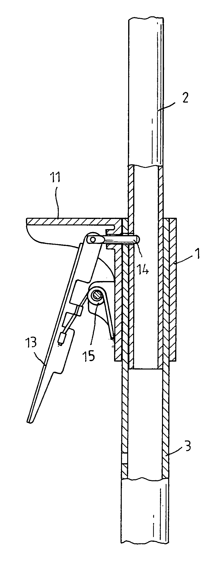
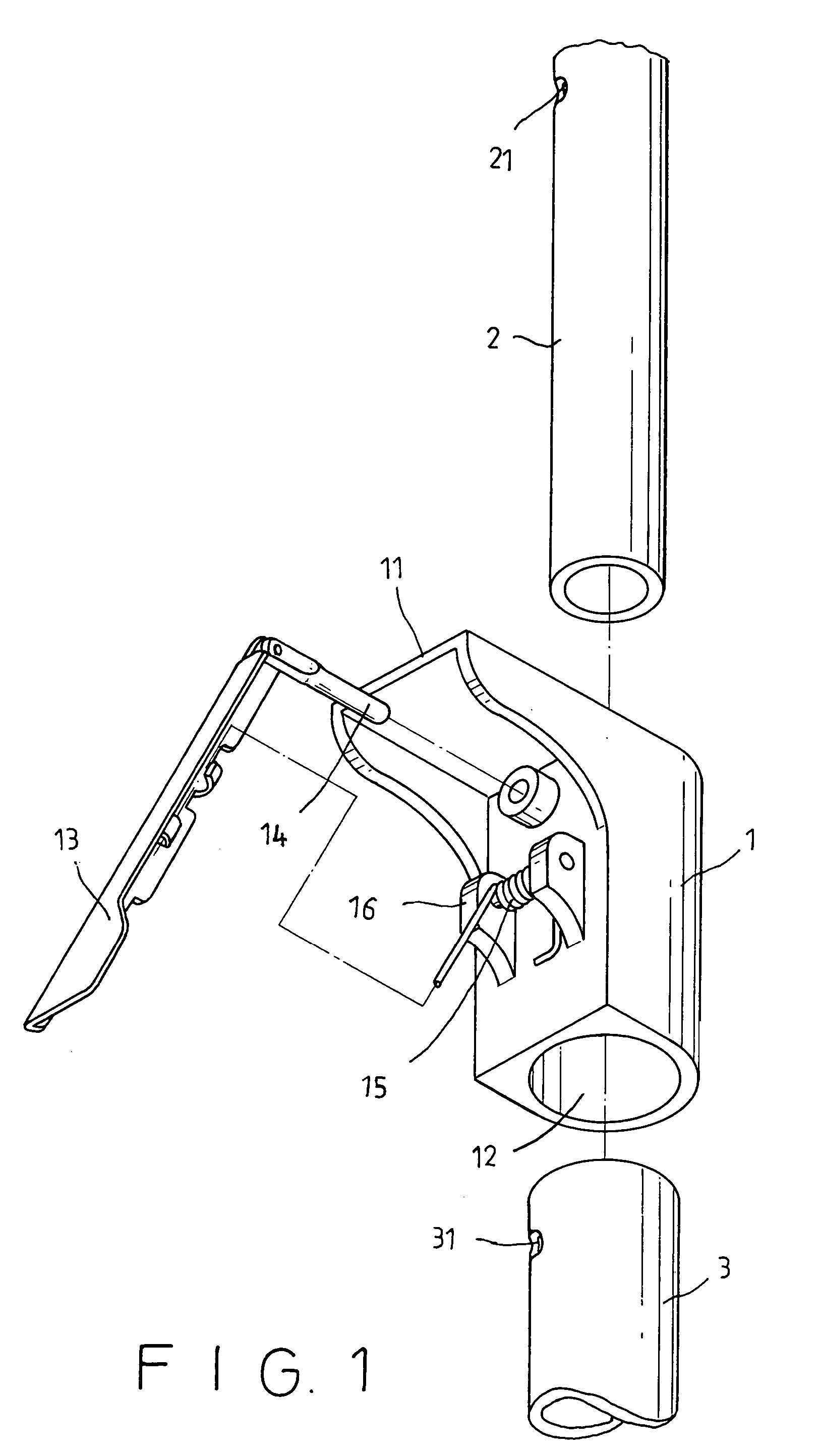
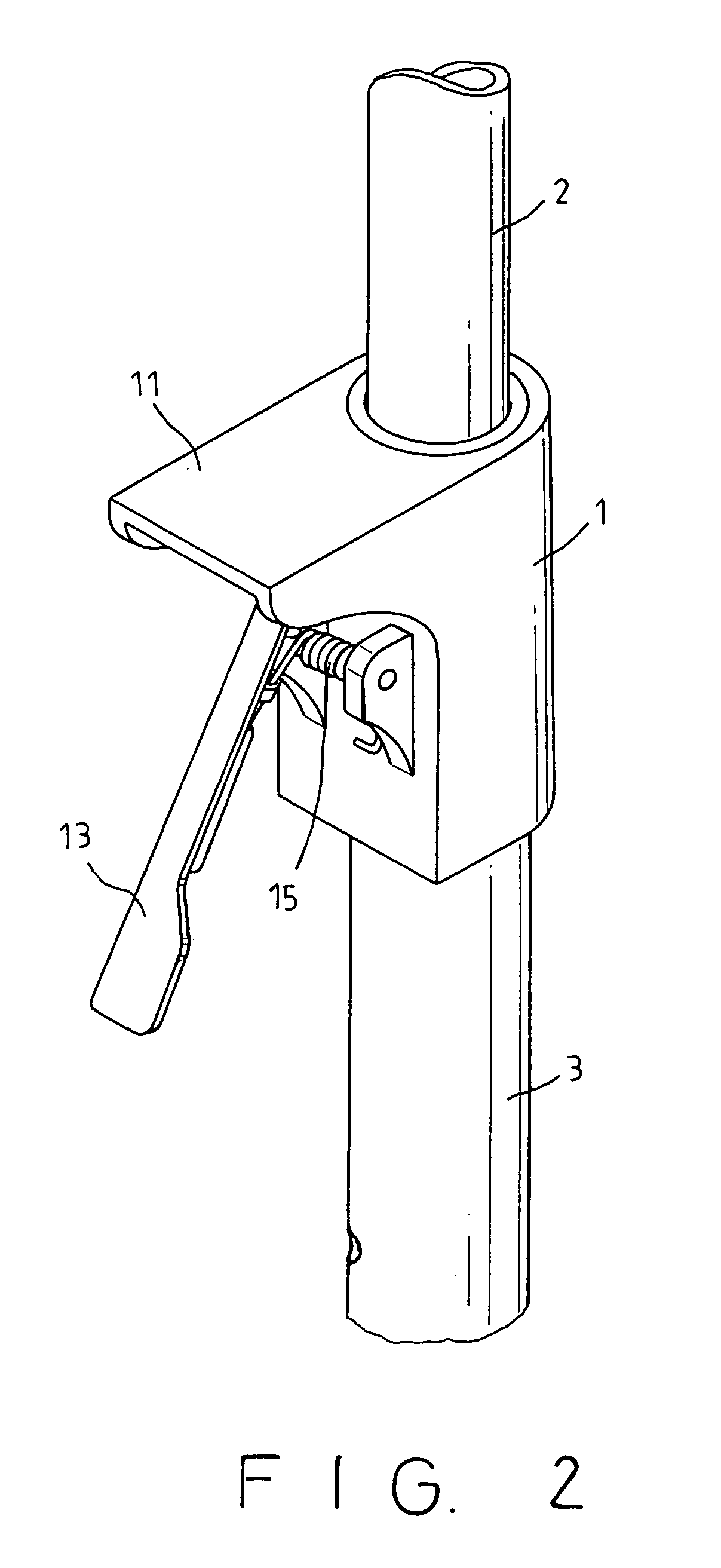
[0009]Referring to FIG. 1 to 4, the present invention relates to a beach umbrella, which has a shaft including an upper tube (2) and a lower tube (3), both with several interval positioned apertures (21), (31) thereon. A positioning apparatus (1) is provided to connect the two tubes together, which has a flat plate (11), a joint (16) with a spring (15) on one side to connect with a handle (13) and to provide elastic force for pushing a rod (14) on top of the handle (13) into central hole (12) of the apparatus (1). As the upper tube (2) and the lower tube (3) are received in the central hole (12) of the positioning apparatus (1), the rod (14) can penetrate one aperture (21) and a relating aperture (31) to position both tubes at the certain position. Hence, the height of the beach umbrella can be determined in secure, wherein both tubes (2), (3) are never loosened.

[0010]When to insert the lower tube (3) into ground of beach, sand or earth, as shown in FIG. 5 to 7, the positioning appa...


PUM


Abstract

A positioning structure of a beach umbrella is provided that includes a positioning apparatus to connect with a lower tube of the umbrella. The apparatus has a flat plate for forcing the lower tube being inserted into ground easily. A handle has a rod to engage with apertures on the tubes of the shaft that can adjust the height of the beach umbrella as desired for increasing utility.

Description

BACKGROUND OF THE INVENTION[0001]A conventional beach umbrella usually includes a shaft and a frame set, wherein the shaft is composed of an upper tube and a lower tube to insert into sand or earth for standing and being used. Since the beach umbrella is used at beach, where the wind is always strong, it should be positioned on ground for resisting the wind. But it is very difficult to insert the shaft of the umbrella into the ground in stable. Moreover, the shaft includes the upper tube and the lower tube, both of which are connected together by compression that will be easily loosened when strong wind blows.[0002]The present invention is to provide a positioning structure of a beach umbrella, which includes a positioning apparatus to engage with the upper tube and the lower tube of the shaft firmly. And the umbrella can be positioned at beach in ease by use of the positioning apparatus that overcomes the drawback of prior arts. Now, accompanying with the following drawings, the ch...

Claims


Application Information

Patent Timeline
Patent Type & Authority Patents(United States)
IPC IPC(8): A01K97/10A45B19/04F16B7/10
CPCF16B7/105Y10T403/32483Y10T403/32508Y10T403/32475Y10T403/7079
Inventor LEE, YOUTH
Owner LEE YOUTH
Why Eureka
Try Eureka