System and method for near-field electromagnetic ranging

a near-field electromagnetic and ranging technology, applied in the field of measuring distance or ranging, can solve the problems of increasing the difficulty of radar detection, the inability to rotate the antenna at a high enough angular velocity, and the need for measurements taken from at least two different sources to achieve even a single range or distance calculation

Inactive Publication Date: 2005-11-08
GAN CORP
View PDF99 Cites 112 Cited by
  • Summary
  • Abstract
  • Description
  • Claims
  • Application Information

AI Technical Summary

Benefits of technology

[0058]It is an object of the present invention to provide an electromagnetic ranging apparatus and method that can be operated asynchronously without requiring synchronization of transmitter to receiver or synchronization among a network of receivers.
[0059]It is a further object of the present invention to provide an electromagnetic ranging apparatus and method that can be operated without an awkward and lengthy calibration process and that can be useful in a wide variety of propagation environments.

Problems solved by technology

In practice, it is not feasible to rotate an antenna at a high enough angular velocity for this effect to be readily observable.
However, a disadvantage to this prior art ranging technique is that obtaining even a single range or distance calculation requires measurements taken from at least two different positions.
Radar works well in the detection of aircraft in an open sky or ships on the surface of an ocean but radar detection becomes increasingly difficult when the target being tracked is in a cluttered environment populated by scatterers of equivalent cross-section to the target one desires to track.
A disadvantage of passive tag ranging is that the effective range tends to be relatively short due to the low power picked up by the tag that is available to be reradiated.
A disadvantage of transponder ranging is that it requires an active target to receive a signal, and transmission of a return signal is generally influenced by some property of the received interrogatory signal.
Second, because the near-fields have such a relatively rapid power roll-off, range tends to be relatively finite and limited.
Inferring range from received signal power or amplitude is problematic at best.
Sullivan's system has the disadvantage of requiring a common time base or synchronization among all receivers in the network.
Any clock drift between the transmit-only target and the receiver results in a range error.
As a practical matter, however, precise synchronization is exceedingly difficult and often expensive to achieve.
If a transmit-only target and a receiver are located within a half wavelength or less of each other, then near-field ambiguities make it difficult to determine an accurate range.
However existing transmit-only ranging systems suffer from significant disadvantages.
Some transmit-only ranging systems are dependent on precise synchronization of a network of receivers that tend to be complex, difficult, and expensive to implement.
Some transmit-only ranging systems are dependent on a similarly difficult synchronization of transmitter and receiver.
No prior art ranging system known to the inventors exploits near-field signal phenomena in performing ranging or distance measurement.
Despite these near-field advantages, to the best of the knowledge of the inventors, no prior art describes a system in which near-field signal phenomena and the predictable behavior of those phenomena as they transition from near-field to far-field behavior are exploited in order to obtain range or distance information.

Method used


Image

  • System and method for near-field electromagnetic ranging
  • System and method for near-field electromagnetic ranging
  • System and method for near-field electromagnetic ranging

Examples


Embodiment Construction

[0082]Overview of the Invention

[0083]The present invention will now be described more fully in detail with reference to the accompanying drawings, in which the preferred embodiments of the invention are shown. This invention should not, however, be construed as limited to the embodiments set forth herein; rather, they are provided so that this disclosure will be thorough and complete and will fully convey the scope of the invention to those skilled in art. Like numbers refer to like elements throughout.

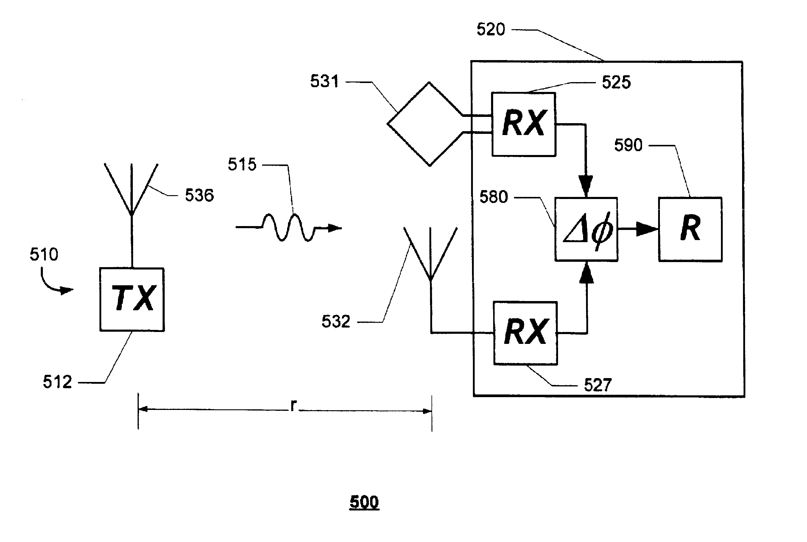
[0084]An Analytic Model

[0085]Suppose a transmit-only target uses a small loop antenna that behaves like a time domain magnetic dipole. A magnetic dipole may be thought of as a small current loop of area A, and a time dependent current I=I0 T(t) where I0 is an initial or characteristic current and T(t) is the time dependence. Assume the dipole lies in the x-y plane centered at the origin with its axis in the z direction. The dipole's magnetic moment m is: m=A I0 T(t), or m=m0 T(t). The...


PUM


Abstract

A system for measuring distance between a first locus and a second locus includes: (a) at least one beacon device; a respective beacon device of the at least one beacon device being situated at the first locus and transmitting a respective electromagnetic signal; and (b) at least one locator device; a respective locator device of the at least one locator device being situated at the second locus and receiving the respective electromagnetic signal. The respective locator device is situated at a distance from the respective beacon device within near-field range of the respective electromagnetic signal. The respective locator device distinguishes at least two characteristics of the respective electromagnetic signal. The respective locator device employs the at least two characteristics to effect the measuring.

Description

[0001]This application claims benefit of prior filed copending Provisional Patent Application Ser. No. 60 / 404,602, filed Aug. 19, 2002, and copending Provisional Patent Application Ser. No. 60 / 404,604, filed Aug. 19, 2002.BACKGROUND OF THE INVENTION[0002]The present invention relates generally to measurement of distance or ranging by exploitation of near-field electromagnetic behavior and especially to a system and method for evaluating a distance between a transmitter or beacon and a receiver or locator. Still more specifically, the present invention describes a means for determining a range to a transmit-only beacon without requiring synchronization, and without relying on variation in signal amplitude. The present invention may be advantageously used as part of a more general system for determining position (range and bearing) or for tracking (determining position in near real time).[0003]Related Art[0004]A variety of techniques are known in the art for using electromagnetic sign...

Claims


Application Information

Patent Timeline
Patent Type & Authority Patents(United States)
IPC IPC(8): G01S11/06G01S11/00G01S5/14G01S13/00G01S13/75G01S5/00G01S19/17
CPCG01S5/14G01S11/06H04B5/0075G01S5/0027G01S5/0081G01S13/75
Inventor SCHANTZ, HANS GREGORYDEPIERRE, ROBERT EDWARD
Owner GAN CORP
Why Eureka
Try Eureka