Self-locating devices via highly directional RFID tags in controlled location

a self-locating device and highly directional technology, applied in the field of rfid technology, can solve the problems of large number of high-logic (active) devices, large amount of power consumption of each high-logic device, and large amount of processing errors, so as to increase the effective range of tags and reduce power consumption

Active Publication Date: 2006-05-04
TOSHIBA GLOBAL COMMERCE SOLUTIONS HLDG
View PDF14 Cites 115 Cited by
  • Summary
  • Abstract
  • Description
  • Claims
  • Application Information

AI Technical Summary

Benefits of technology

[0014] In one implementation, the RFID tags are placed in a waveguide tuned to the tags operating frequency and application. Utilization of the waveguide also increases the tags effective range (directionally) and possibly reduces the amount of power required to interrogate the tag.

Problems solved by technology

Typical RFID tags are omni-directional or wide viewing angle devices that do not lend themselves to receiving or producing directional signals.
Because of this limitation, locating the particular RFID tag requires utilization of multiple RF interrogation devices.
This process often yields errors due to attenuation of RFID signal strength, etc.
Use of such a large number of high-logic (active) devices tends to be rather costly.
Each high logic device is substantially more expensive to obtain than the low-logic tags.
Also additional expense is incurred because each interrogating device must be powered and a central processing system that performs the triangulation calculations must be provided.
Also, the triangulation method is inherently inaccurate because signal strength of the tag received by respective devices varies due to attenuation and other factors.
The substantial cost in implementing the above described device locating system by using a large number of high-logic devices limits the ability to implement the system on a large scale.
Additionally, with current methods, there is no way to inform the user of the user's location relative to the RFID sensors, absent a feedback to the user of the results of the triangulation.

Method used


Image

  • Self-locating devices via highly directional RFID tags in controlled location
  • Self-locating devices via highly directional RFID tags in controlled location
  • Self-locating devices via highly directional RFID tags in controlled location

Examples


Embodiment Construction

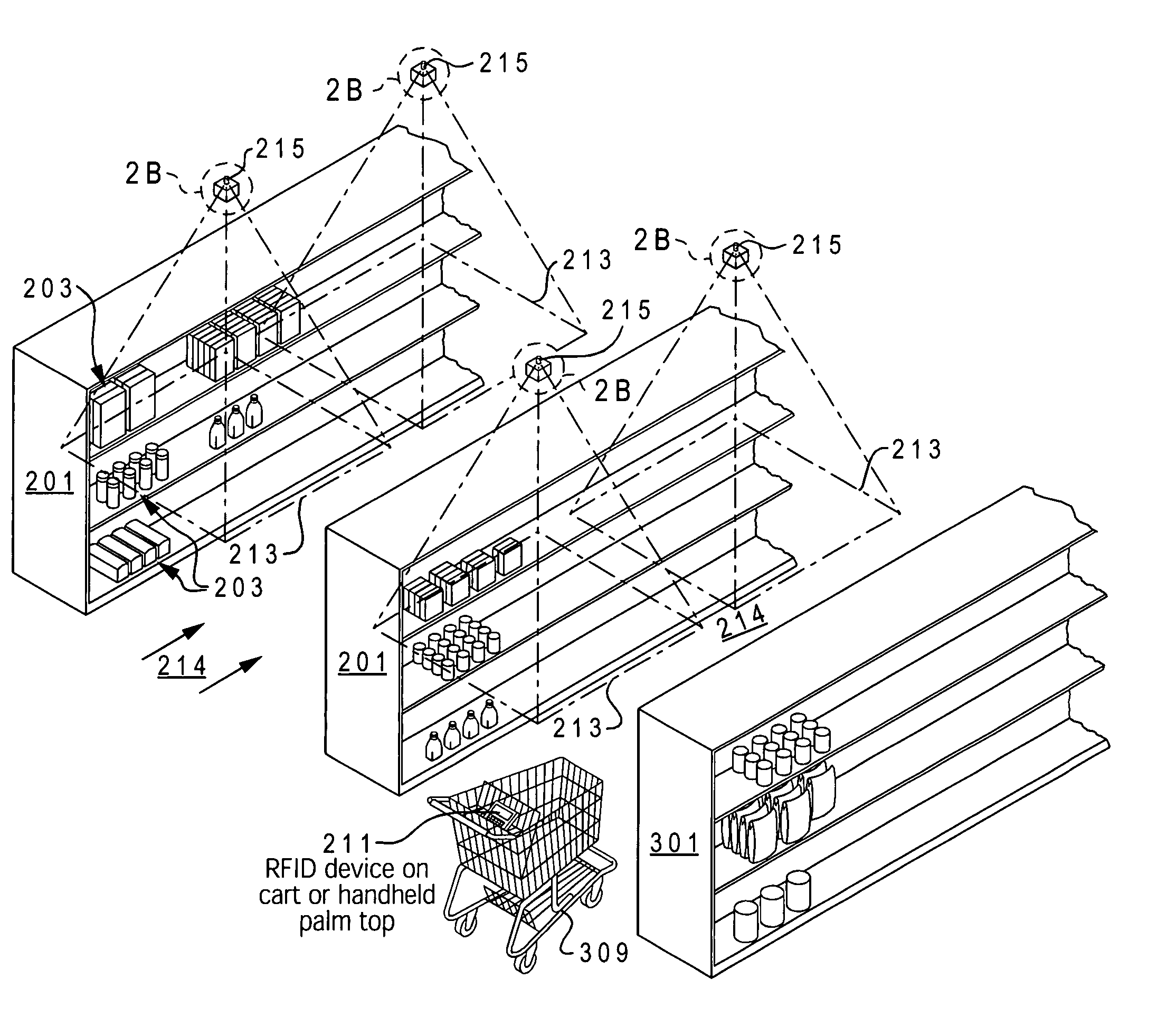
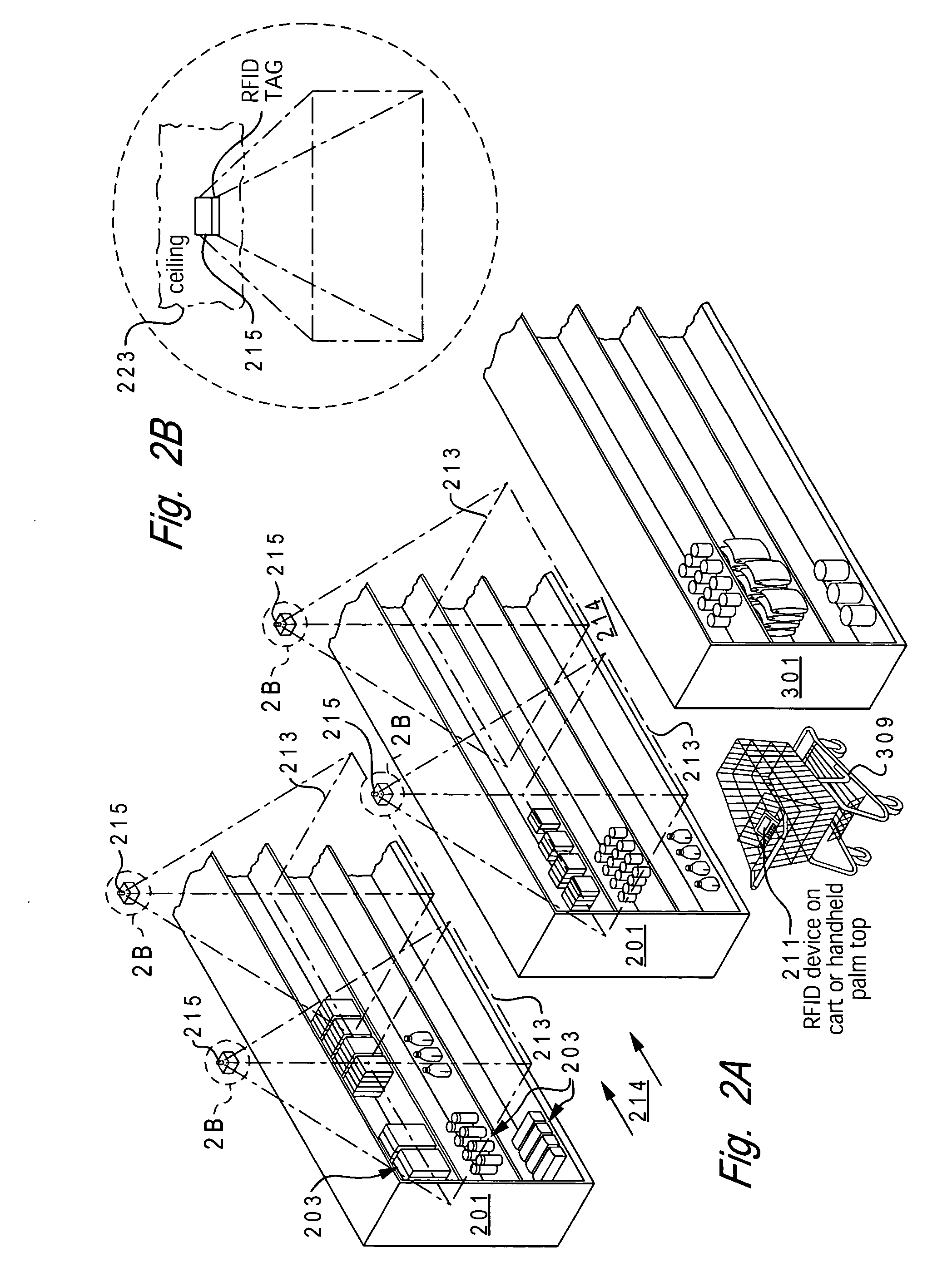
[0024] The present invention provides a method and system for enabling cost-effective location sensing of a device via radio frequency (RF) technology in a monitored environment. A monitored area is provided multiple RFID tags placed at defined coordinates / location throughout the extended area. These RFID tags respond to receipt of a RF signal by transmitting / broadcasting their unique identifier (ID) within the specific area in which the tag is located. The broadcast may be directional based on a pre-set waveguide utilized when mounting the RFID tags.

[0025] In one implementation, the RFID tags are placed in a waveguide tuned to the tags operating frequency. Utilization of the waveguide also increases the tags effective range (directionally) and may reduce the amount of power required to interrogate the tag.

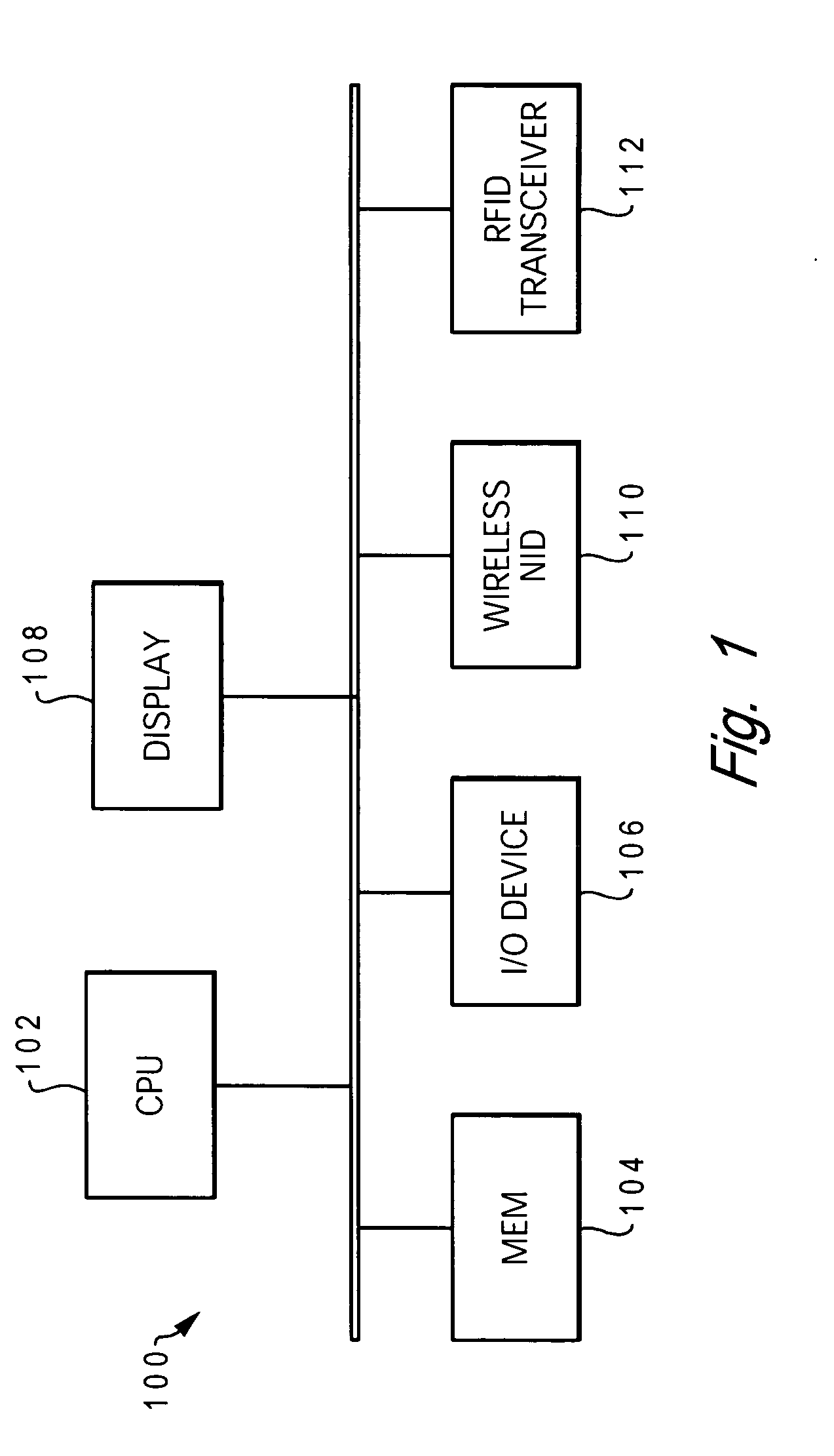
[0026] A device, whose location within the monitored area is desired to be known (or determined), is equipped with an RFID interrogating device, such as an RF transceiver, which...


PUM


Abstract

A monitored area is provided multiple RFID tags placed at defined coordinates / locations throughout the extended area. These RFID tags respond to receipt of a RF signal by transmitting / broadcasting their unique identifier (ID) within the specific area in which the tag is located. A device, whose location within the monitored area is desired, is equipped with an RFID interrogating device, such as an RF transceiver, which periodically broadcasts RF interrogation signals. The multiple RFID tags are positioned at specific areas within the environment to allow the RF interrogating device to (1) receive the RFID signal and (2) utilized the received data to independently determine the device's location.

Description

BACKGROUND OF THE INVENTION [0001] 1. Technical Field [0002] The present invention relates in general to RFID technology, and in particular to a method and system for using RFID technology to locate devices. Still more particularly, the present invention relates to a method and system for cost-effectively locating devices using RFID technology. [0003] 2. Description of the Related Art [0004] The use of radio frequency (RF) identification (RFID) technology to locate devices that are equipped with an RFID tag (i.e., an electronic tag that emits an RFID signal when triggered by an RF signal) is generally known in the art. In conventional systems, a number of RF transceivers are provided in a monitored environment. These transceivers generate and transmit RF signals in a particular sub-area defined by the strength of the RF signal and location of the RF transceiver relative to the area of projection. [0005] Thus, in a retailed environment, for example, the RF transceivers may be placed ...

Claims


Application Information

Patent Timeline
Patent Type & Authority Applications(United States)
IPC IPC(8): G01S13/78G01C21/26G08B1/08G08B5/22G08G1/123
CPCG01C3/26G01S5/0252G01S5/14G01S13/765G06K17/00G06K2017/0045G06Q30/0207G06Q30/0241G08B21/0258G08B21/0272G08B21/0275G01S5/02529
Inventor STEINER, DAVID JOHN
Owner TOSHIBA GLOBAL COMMERCE SOLUTIONS HLDG
Why Eureka
Try Eureka