
Contact module in which mounting of contacts is simplified

a contact module and contact technology, applied in the direction of securing/insulating coupling contact members, coupling device connections, semiconductor/solid-state device details, etc., can solve the problems of complex production process of terminal assemblies, overmolding of expensive die assemblies, and complicated assembly of connecting bodies, etc., to achieve simplified production process, reduced cost, and reduced number of parts

Inactive Publication Date: 2006-08-29
JAPAN AVIATION ELECTRONICS IND LTD
View PDF7 Cites 94 Cited by
  • Summary
  • Abstract
  • Description
  • Claims
  • Application Information

AI Technical Summary

Benefits of technology

The present invention provides a contact module that is cheaper, has fewer parts, and has a simpler production process. The contact module includes a conductive contact and an insulator that holds the contact. The insulator has a groove that holds the contact's intermediate portion, and the contact has a positioning-subject portion. The insulator also has a retaining portion that keeps the contact's intermediate portion in place. The invention also provides a connector that uses the contact module. The contact module can be stacked together to create a more compact connector. Overall, the invention simplifies the process of creating and using contact modules, making them more efficient and cost-effective.

Problems solved by technology

However, an expensive die assembly is required for overmolding the lead frame with the insulator.
Further, the production process of the terminal assembly is complicated.
However, since the two resin members having different shapes are employed, the number of parts becomes large, two kinds of expensive die assemblies are required, and further, the assembling process of the connecting body becomes complicated.

Method used


Image

  • Contact module in which mounting of contacts is simplified
  • Contact module in which mounting of contacts is simplified
  • Contact module in which mounting of contacts is simplified

Examples


Embodiment Construction

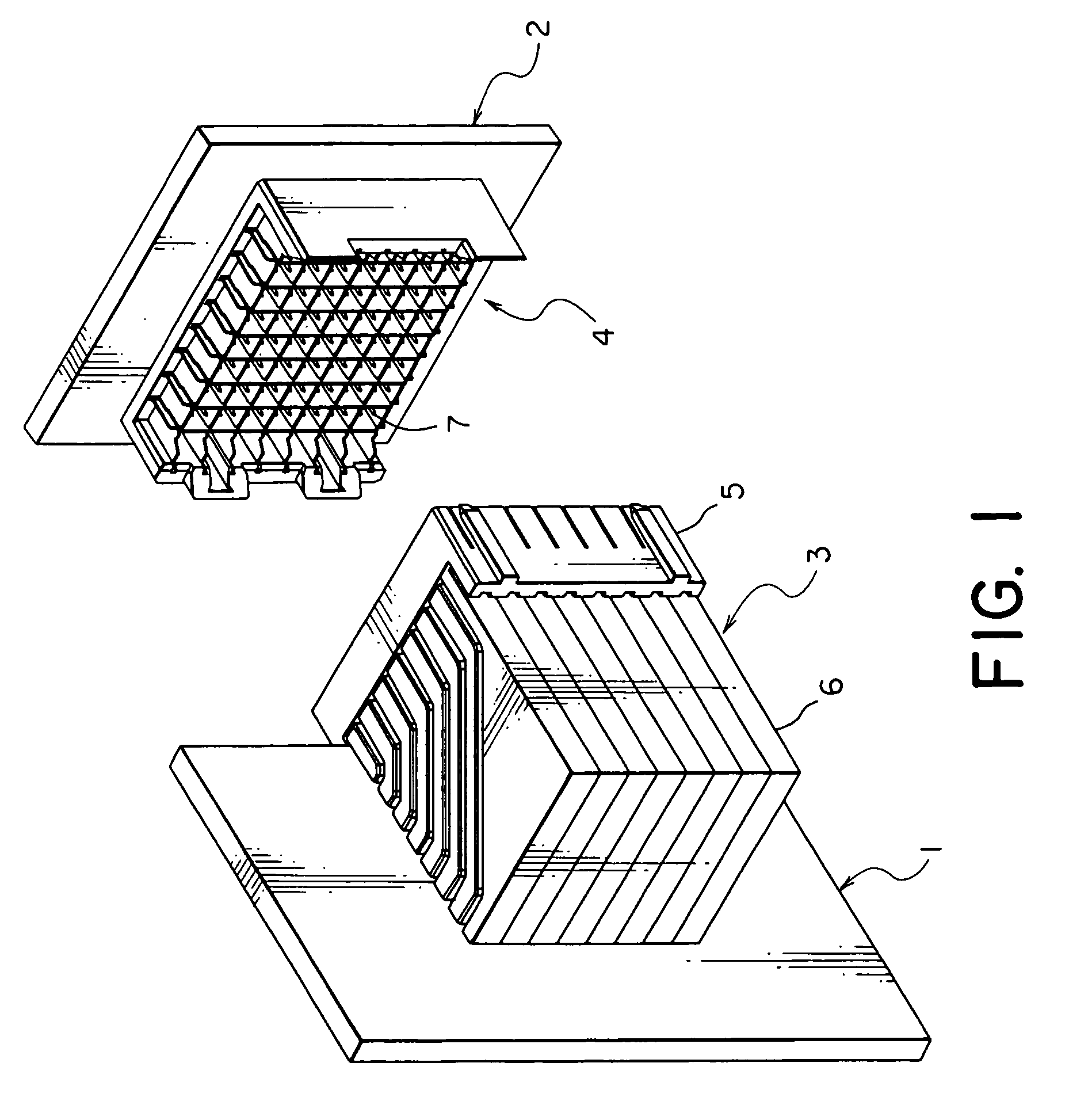
[0041]Referring to FIG. 1, description will be made of a connector according to a preferred embodiment of the present invention.

[0042]The connector illustrated in FIG. 1 serves to electrically connect between a backplane 1 and a midplane 2 each being a circuit board, and is in the form of a plug connector 3 press-fitted to the backplane 1. A receptacle connector 4 is press-fitted to the midplane 2. When the plug connector 3 is fitted into the receptacle connector 4, the backplane 1 and the midplane 2 are electrically connected to each other.

[0043]The plug connector 3 comprises a front housing 5 and eight contact modules 6 attached to the front housing 5. The receptacle connector 4 has a number of pin contacts 7 arranged in a matrix.

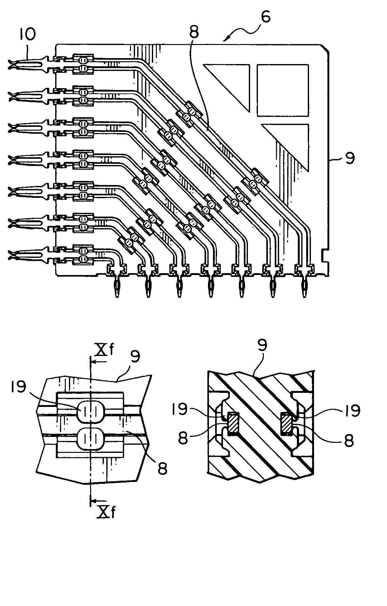
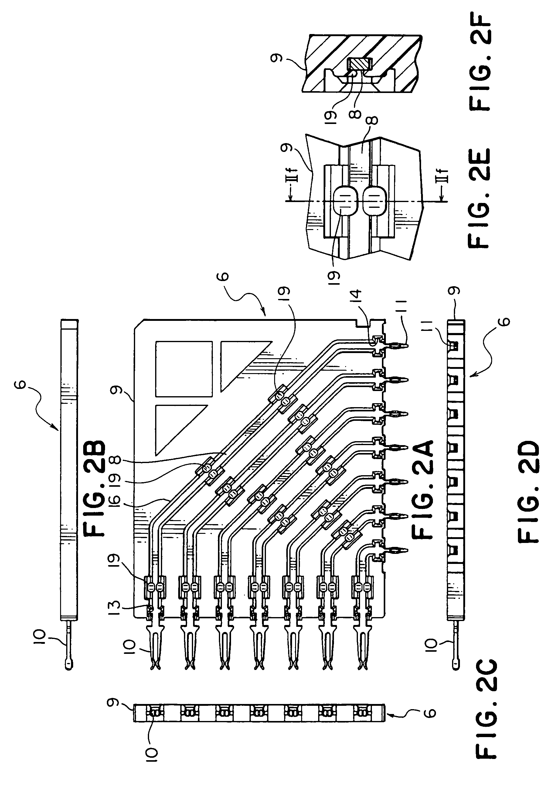
[0044]Referring to FIGS. 2A to 2F, the contact modules 6 will be described.

[0045]Each contact module 6 comprises seven socket contacts 8 and a molded member made of an insulating material, i.e. an insulator 9. The socket contacts 8 are mounted on the insu...


PUM


Abstract

A contact module includes a plurality of conductive contacts and an insulator retaining the contacts. Each of the contacts includes a contact portion at one end thereof, a terminal portion at the other end thereof, and an intermediate portion extending between the contact portion and the terminal portion. The intermediate portion has a positioning-subject portion. The insulator includes grooves each receiving therein the intermediate portion of the corresponding contact, positioning portions each positioning the positioning-subject portion of the corresponding contact, and retaining portions each retaining the intermediate portion of the corresponding contact. The positioning-subject portions of the contacts are press-fitted into the positioning portions of the insulator so that the contacts are provisionally retained by the insulator. By the use of the retaining portions, the contacts are finally retained by the insulator.

Description

BACKGROUND OF THE INVENTION[0001]The present invention relates to a contact module having an insulator and a conductive contact mounted on the insulator, and further relates to a connector using such a contact module.[0002]A connector of the type is disclosed in, for example, Japanese Patent (JP-B) No. 2537698 and comprises a plurality of contact modules each called a terminal assembly, which are stacked together. Each contact module comprises a plurality of conductive terminals and an insulator overmolded on the terminals to retain them. In the production of each terminal assembly, a lead frame having a plurality of terminals is obtained by pressing a metal plate. An insulator is overmolded on the lead frame, then an unnecessary part of the lead frame is cut off.[0003]The connector is suitable for electrically connecting between two boards arranged perpendicular to each other. However, an expensive die assembly is required for overmolding the lead frame with the insulator. Further,...

Claims


Application Information

Patent Timeline
Patent Type & Authority Patents(United States)
IPC IPC(8): H01R13/648H01L27/01H01R13/658H01R12/72H01R12/79H01R13/41H01R13/514
CPCH01R13/41H01R23/7073H01R12/724
Inventor NAKADA, KOUJI
Owner JAPAN AVIATION ELECTRONICS IND LTD
Learn More