1:N protection in an optical terminal

a technology of optical terminals and optical terminals, applied in the field of optical communication networks, can solve the problems of b>100/b> and b>200/b> being generally expensive, and the network described does not provide any failure protection for unprotected terminals

Inactive Publication Date: 2006-08-29
TELLABS OPERATIONS
View PDF41 Cites 94 Cited by
  • Summary
  • Abstract
  • Description
  • Claims
  • Application Information

AI Technical Summary

Benefits of technology

[0023]In accordance with a further embodiment of this invention, a communications network is provided which includes both of ...

Problems solved by technology

Unfortunately, the above-described network has drawbacks in that it requires the use of many protection components (e.g., transponders 104-1 to 104-n) in the nodes 100 and 200, and thos...

Method used


Image

  • 1:N protection in an optical terminal
  • 1:N protection in an optical terminal
  • 1:N protection in an optical terminal

Examples


Embodiment Construction

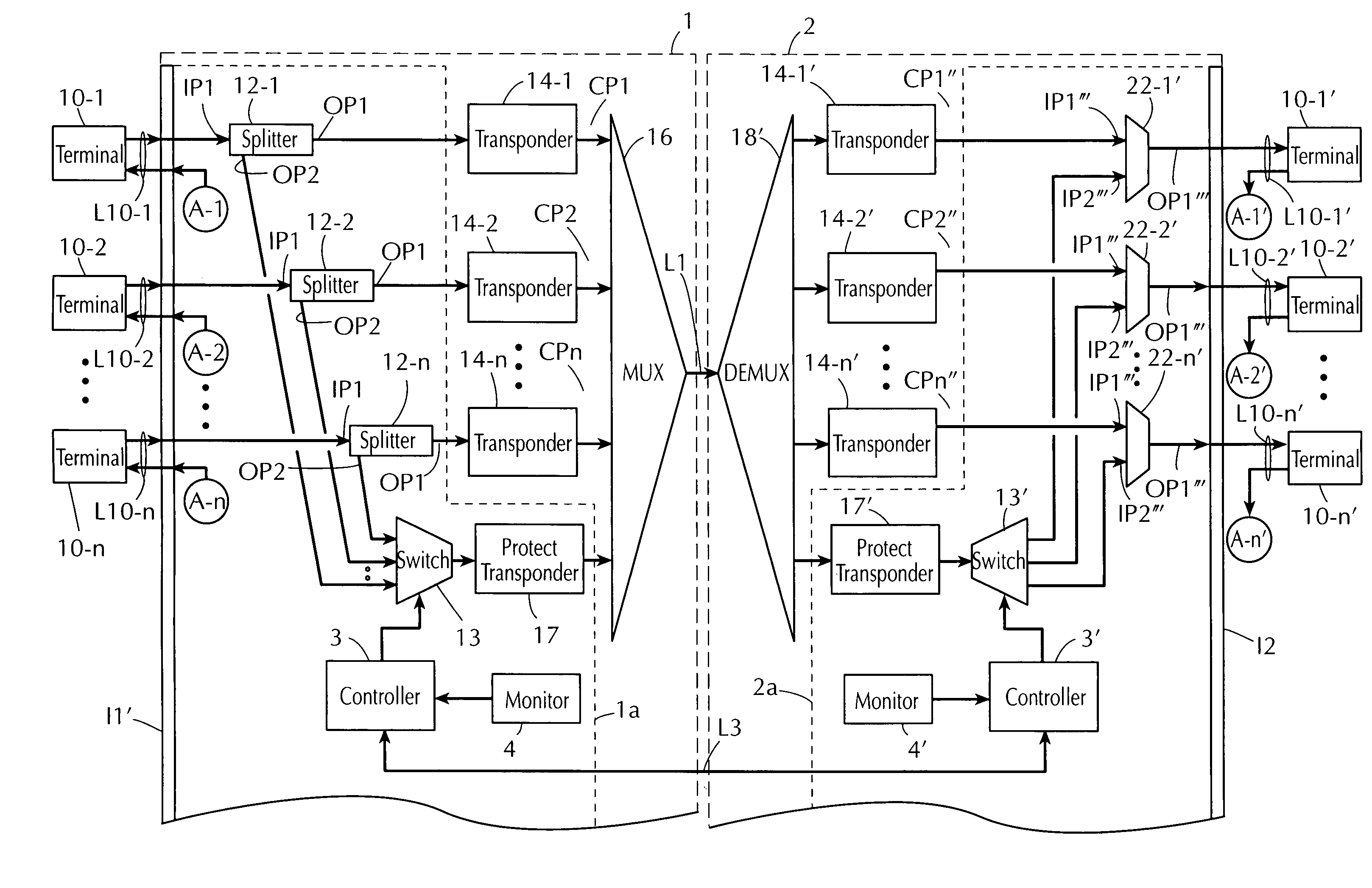
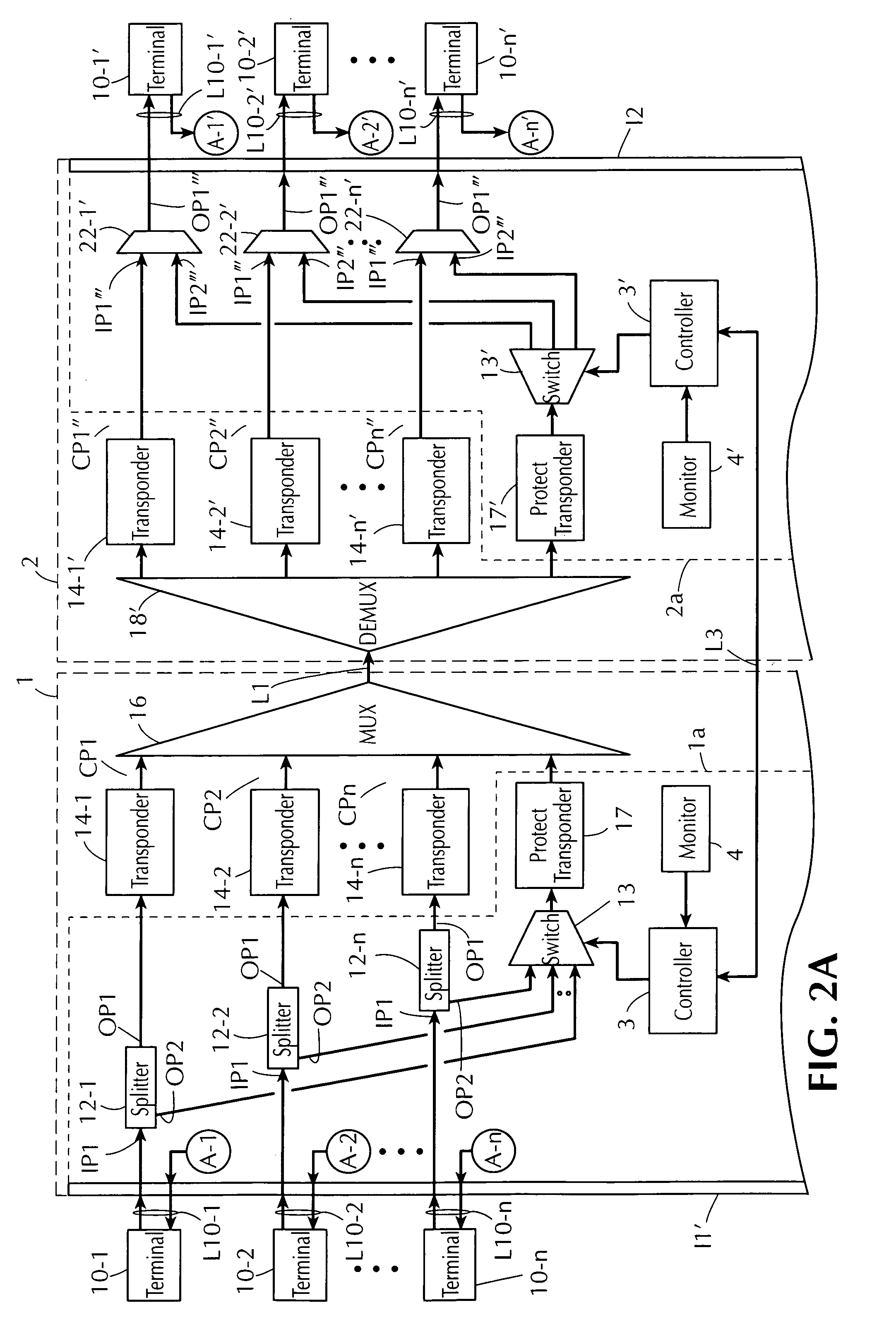
[0032]FIGS. 2a and 2b illustrate a block diagram of a plurality of nodes (also referred to as optical line terminals (OLTs)) 1 and 2 and terminals 10-1 to 10-n and 10-1′ to 10-n′ of an optical communications network that is suitable for practicing this invention. The network is depicted as a point-to-point communications network, although the invention is not limited to being employed only in such networks. For example, the invention may also be implemented in a mesh or point-to-multipoint (chain) communications network.

[0033]The nodes 1 and 2 are coupled together via transmission links L1, L2, and L3, each of which may include, for example, one or more optical fibers (e.g., two unidirectional fibers). In other embodiments of the invention, two or all three of the communication links L1, L2, and L3 may be combined into a single fiber link. The terminals 10-1 to 10-n are bidirectionally coupled to an interface I1 of the node 1 via “working” communication links L10-1 to L10-n, respect...


PUM


Abstract

A communication network includes first and second terminals, nodes, and links. The first node is coupled to the first terminal through the first link, and coupled to the second terminal through the second link and the second node. The first node preferably includes communication paths, each coupled to one corresponding first link and to the second link, through a multiplexing device, and routing signals between the links. The first node also preferably includes an alternate communication path coupled through the multiplexing device to the second link, a switch coupled to the alternate path, and a detector detecting failure of a communication path. A controller is responsive to the detector detecting a failure in a communication path and controls the switch to couple the alternate path to a corresponding first link, thereby enabling a signal to be routed between that first and second links through the alternate path.

Description

FIELD OF THE INVENTION[0001]This invention relates generally to optical communications networks, and, in particular, to an apparatus for providing 1:N (“one-to-N”) protection in an optical terminal of a Wavelength-Division Multiplexed (WDM) multi-channel optical communications network.BACKGROUND OF THE INVENTION[0002]It is known to provide protection in optical networks against line failures, node failures, and the like, by equipping such networks with bypass equipment for bypassing failed components and routing signals to their intended destinations. An example of a prior art network that includes bypass equipment is depicted in FIG. 1. The network includes optical line terminals (OLTs), or nodes, 100 and 200, and a plurality of terminals 100-1 to 100-n, 200-1 to 200-n. The nodes 100 and 200 are bidirectionally coupled to one another through a bidirectional transmission link (L).[0003]The node 100 comprises a plurality of bidirectional communication paths P-1 to P-n and P-1′ to P-n...

Claims


Application Information

Patent Timeline
IPC IPC(8): H04B10/00H04Q11/00
CPCH04J14/0295H04Q11/0062H04J14/0279H04Q2011/0083H04Q2011/0081
Inventor GERSTEL, ORNAN A.
Owner TELLABS OPERATIONS
Why Eureka
Try Eureka