Valve, In Particular A Suction Valve, In A High-Pressure Pump of A Fuel Injection System

a technology of high-pressure pump and valve body, which is applied in the direction of valve operating means/release devices, fuel injecting pumps, machines/engines, etc., can solve the problems of component joint and/or seal failure during the life of the valve, and the loss of the functioning of the suction valv

Active Publication Date: 2019-01-03
ROBERT BOSCH GMBH
View PDF28 Cites 1 Cited by
  • Summary
  • Abstract
  • Description
  • Claims
  • Application Information

AI Technical Summary

Problems solved by technology

Since the impulse force can reach high levels as the magnet armature and pole core collide, this can lead to failure of the component joints and / or seals during the life of the valve.
This may result in leaks and / or a loss of functioning of the suction valve.

Method used


Image

  • Valve, In Particular A Suction Valve, In A High-Pressure Pump of A Fuel Injection System
  • Valve, In Particular A Suction Valve, In A High-Pressure Pump of A Fuel Injection System
  • Valve, In Particular A Suction Valve, In A High-Pressure Pump of A Fuel Injection System

Examples


Embodiment Construction

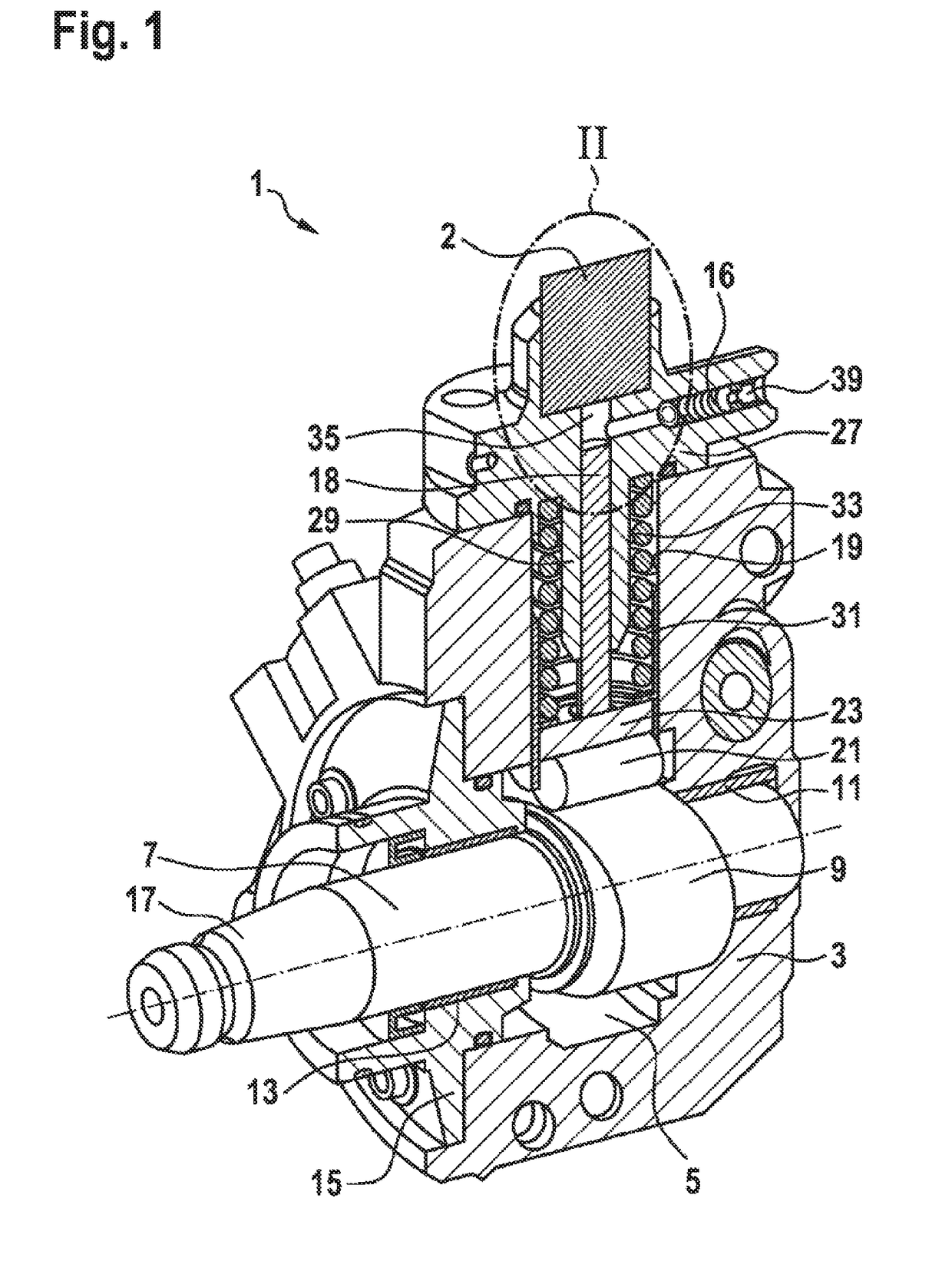
[0025]FIG. 1 shows a section through a schematically illustrated high-pressure pump 1, which is designed as a high-pressure fuel pump and is preferably installed in a common rail injection system. By means of the high-pressure pump 1, fuel supplied by a low-pressure fuel system, which has at least one tank, a filter and a low-pressure pump, is pumped into a high-pressure reservoir, from which the fuel stored there is removed by fuel injectors for injection into associated combustion chambers of a combustion engine. The fuel is transferred to a pump working space 35 by an electromagnetically controllable suction valve 2, wherein the electromagnetically controllable suction valve, which will be explained below, is installed on the high-pressure pump 1.

[0026]The high-pressure pump 1 has a pump housing 3 with a camshaft space 5. A camshaft 7 having a cam 9 designed as a double cam, for example, projects into the camshaft space 5. The camshaft 7 is supported in two bearings arranged on b...


PUM


Abstract

The invention relates to a valve, in particular a suction valve, in a high-pressure pump of a fuel injection system, in particular a common rail injection system, comprising a magnet actuator (22) which has a magnet coil (6), a magnet armature (10) that moves in a stroke-like manner, and a pole core (20), wherein the magnet armature (10) and the pole core (20) together limit a working air gap (28), and the magnet armature (10) can at least indirectly contact the pole core (20), wherein the valve also has a valve element (14) which can be moved between an open position and a closed position, and which is at least indirectly in mechanical contact with the magnet armature (10). According to the present invention, a separate magnet armature insert (8) arranged in the magnet armature (10) and/or a separate pole core insert (24) arranged in the pole core (20) is provided in the contact area of the magnet armature (10) on the pole core (20), in order to achieve a separation of the mechanical and magnetic forces. The invention also relates to a high-pressure pump with a suction valve of this type.

Description

[0001]The invention relates to a valve, in particular a suction valve, in a high-pressure pump of a fuel injection system, in particular a common rail injection system, having the features in the preamble of claim 1.PRIOR ART[0002]A valve, in particular an electromagnetically controllable suction valve, of a high-pressure pump of a fuel injection system, in particular a common rail injection system, is known from DE 10 2013 220 593 A1. The high-pressure pump having a suction valve of this kind is furthermore known from this document.[0003]The suction valve has a valve element which can be moved between an open position and a closed position, and which is acted upon by the spring force of a first compression spring in the closed position. The valve element is in contact at least indirectly with a magnet armature via an armature pin. By means of the magnet armature, it is thus possible to transmit an actuating force to the valve element. The high-pressure pump has a pump housing havin...

Claims


Application Information

Patent Timeline
Patent Type & Authority Applications(United States)
IPC IPC(8): F02M59/36F02M63/00
CPCF02M59/368F02M63/0021F02M63/007F02M2200/02F02M63/00F16K31/0658F02M59/36F16K31/06F16K31/0655
Inventor LANGENBACH, CHRISTIANLUCARELLI, FRANCESCO
Owner ROBERT BOSCH GMBH
Why Eureka
Try Eureka