Hydraulic tool

a hydraulic tool and tool body technology, applied in the field of hydraulic tools, can solve the problems of not being stably held by the single hand, the hydraulic tool the building cannot be normally opened, etc., and achieve the effect of stably holding

Inactive Publication Date: 2006-09-05
OGURA
View PDF14 Cites 20 Cited by
  • Summary
  • Abstract
  • Description
  • Claims
  • Application Information

AI Technical Summary

Benefits of technology

[0011]When using the hydraulic tool of the present invention, the operator is able to grip the grip with one hand and to grip the grip handle with the other hand, and is able to operate the spool valve by turning the grip handle gripped by the hand. Therefore, the hydraulic tool can be stably held and the working tool is able to perform opening and closing operations with reliability even if the hydraulic tool needs to exert a strong force on an object.

Problems solved by technology

There are situations where doors need to be pried open during rescue operations, such as when a door of an automobile cannot be normally opened due to deformation of the automotive body caused by a traffic accident, or a door of a building cannot be normally opened due to the deformation of the building caused by an earthquake or a fire.
However, when the hydraulic tool is large or when the hydraulic tool needs to be pressed against a door or the like during a prying operation, the hydraulic tool cannot be stably held by the single hand and it is difficult to press the tip of the working tool firmly against the door or the like.
Since a finger of the hand gripping the grip is placed on the slide handle, it is difficult to hold the hydraulic operating device firmly.
Since the slide handle needs to be operated to operate the spool valve, the grip cannot be turned relative to a main casing, the positional relation between the grip and the main casing is fixed, and hence the operability of the hydraulic tool is unsatisfactory.

Method used


Image

  • Hydraulic tool
  • Hydraulic tool
  • Hydraulic tool

Examples


Embodiment Construction

[0020]A hydraulic tool in a preferred embodiment according to the present invention will be described with reference to the accompanying drawings.

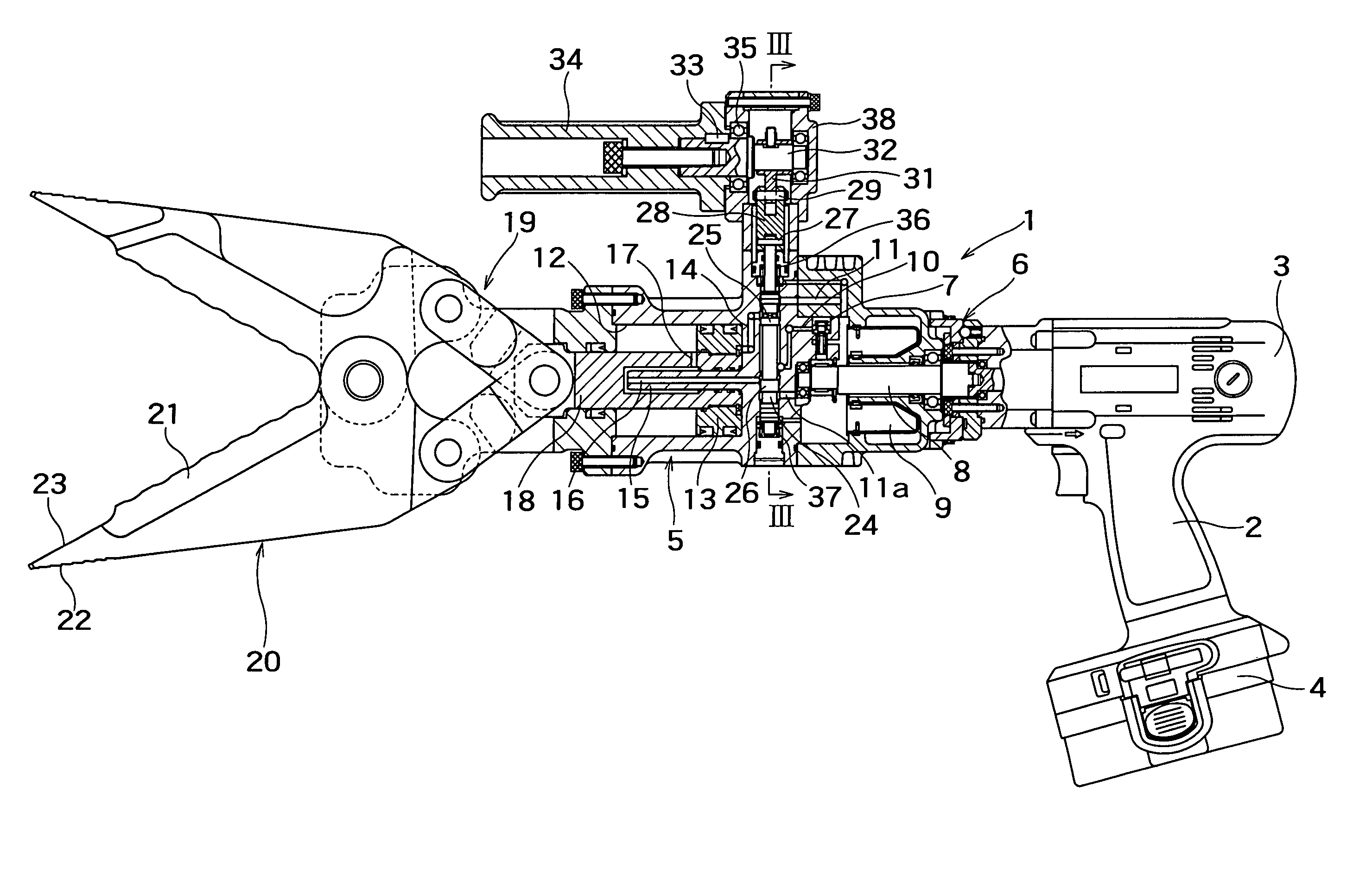
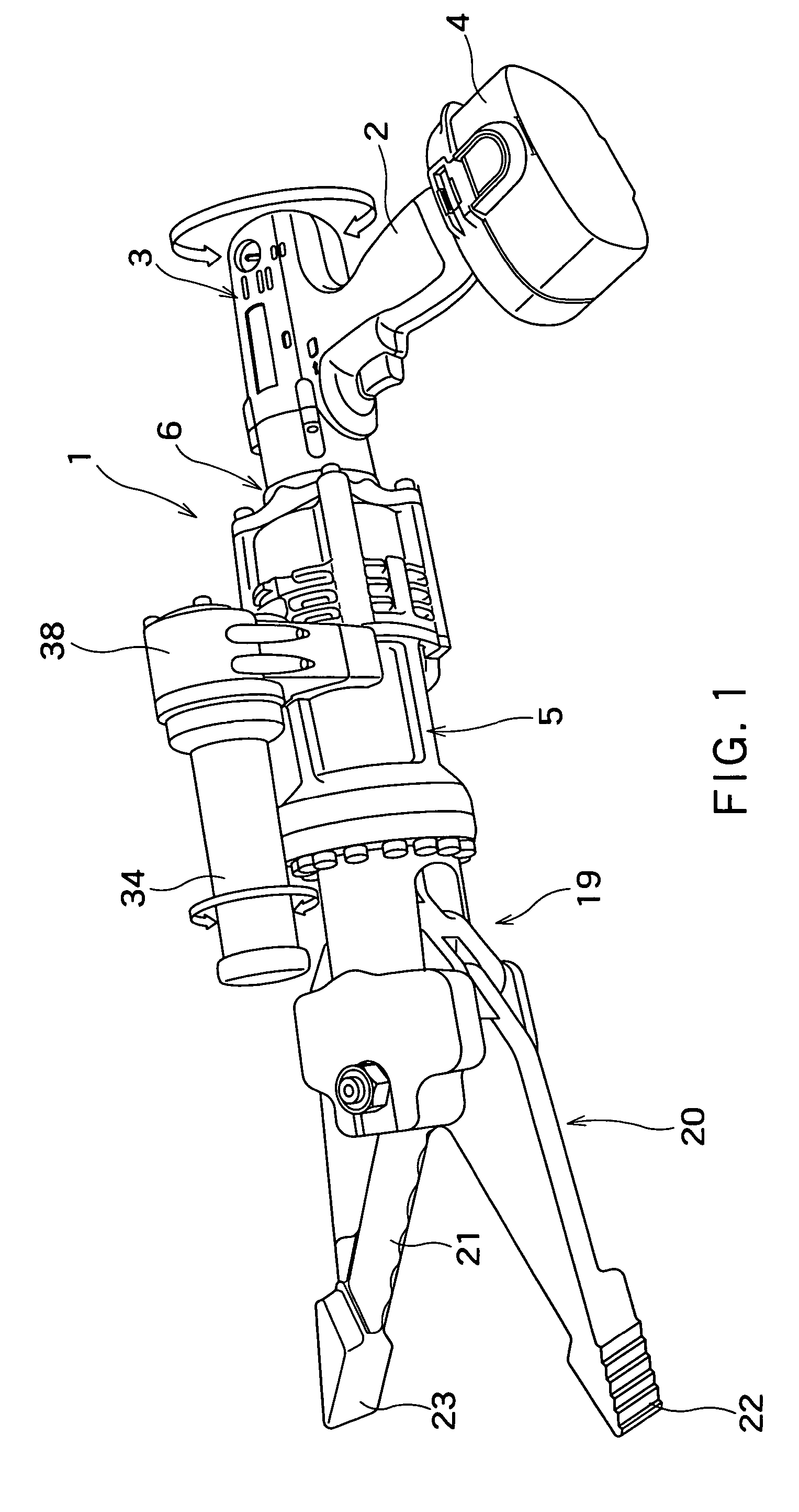
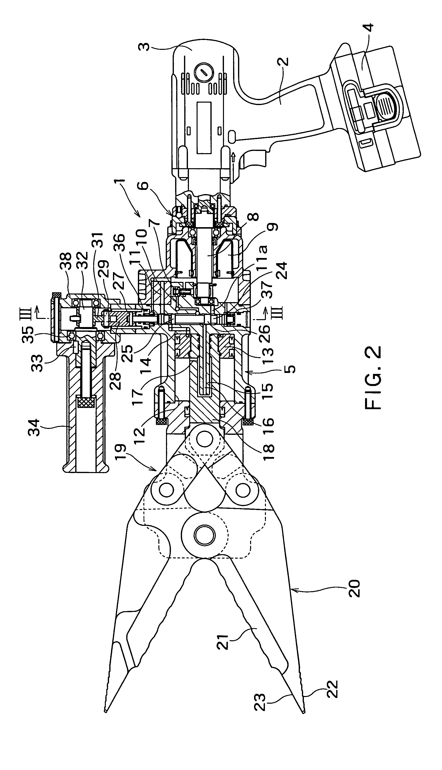
[0021]FIGS. 1 and 2 are a perspective view and a cross-sectional view, respectively, of a hydraulic tool 1 in a preferred embodiment according to the present invention. Referring to FIGS. 1 and 2, the hydraulic tool 1 includes an electric motor 3 having a grip 2 resembling a pistol grip, a main casing 5 connected by a rotary mechanism 6 to the electric motor 3 so as to be turnable, and a working tool 20 connected to a front part of the main casing 5 by a linkage 19.

[0022]A battery case 4 containing a battery, namely, a power source for the electric motor 3, is joined to the lower end of the grip 2 of the electric motor 3. A drive shaft 8 of the electric motor 3 is extended into the main casing 5 to drive a hydraulic power generating mechanism 7.

[0023]The hydraulic power generating mechanism 7 generates hydraulic power by using the working ...


PUM

PropertyMeasurementUnit
forceaaaaaaaaaa
hydraulic poweraaaaaaaaaa
resilienceaaaaaaaaaa

Abstract

A hydraulic tool is provided with a spool valve 24 for changing the flow of a working fluid pressurized by a hydraulic power generating mechanism in a hydraulic circuit. The spool valve 24 is slidable in directions perpendicular to a piston rod 18. A cylindrical grip handle 34 to be operated by the operator's hand is extended parallel to the piston rod 18 on the outer surface of the main casing 5 so as to be turnable about its own axis. The spool valve 24 and the grip handle 34 are interlocked by a cam mechanism including members 29, 30 and 21. The spool valve 24 is moved axially by turning the grip handle 34 to control the flow direction of the working fluid.

Description

TECHNICAL FIELD[0001]The present invention relates to a hydraulic tool including a working tool provided with cutting blades or prying jaws to be operated by a hydraulically operated piston and, more particularly, to an easy-to-operate hydraulic device.BACKGROUND ART[0002]There are situations where doors need to be pried open during rescue operations, such as when a door of an automobile cannot be normally opened due to deformation of the automotive body caused by a traffic accident, or a door of a building cannot be normally opened due to the deformation of the building caused by an earthquake or a fire. Usually, a portable, hydraulic cutting and expanding tool generally called Combi Tools are used to open such a stuck door.[0003]The applicant of the present patent application developed a portable, hydraulic tool capable of being easily operated by an operator and made a patent application for an invention related to the portable, hydraulic tool in Jpn. Pat. App. No. 2000-273697 an...

Claims


Application Information

Patent Timeline
Patent Type & Authority Patents(United States)
IPC IPC(8): B23D29/00B26D5/08A62B3/00B23D15/14B23D17/06B25F5/00B26D5/12F15B15/06
CPCB23D15/14B25F5/005B23D29/00B23D17/06A62B3/005
Inventor OIDE, EISUKE
Owner OGURA
Why Eureka
Try Eureka