Electromechanically-assisted regulator control assembly

a control assembly and electronic mechanical technology, applied in the direction of fluid pressure control, process and machine control, instruments, etc., can solve the problems of “over breathing” the regulator, slow response of the prior art scba regulator to very rapid breathing transients, and reducing the pressure of the facepi

Inactive Publication Date: 2006-09-05
CREARE INC
View PDF19 Cites 97 Cited by
  • Summary
  • Abstract
  • Description
  • Claims
  • Application Information

AI Technical Summary

Benefits of technology

[0007]In another aspect, the present invention is directed a regulator control assembly for use in a second-stage regulator. The regulator control assembly includes a pilot chamber, a single air supply line used to supply air to a SCBA facepiece, a mechanical actuator sub-assembly for depressurizing the pilot chamber, and an electromechanical actuator sub-assembly for depressurizing the pilot chamber.
[0008]In a further aspect, the present invention is directed to a regulator control assembly for use in a second-stage regulator having a pressure-sensitive valve controlling a single air supply line. The regulator control assembly includes first means for actuating the pressure-sensitive valve. The first means includes a mechanically actuated element. The regulator control assembly also includes second means for actuating the pressure-sensitive valve. The second means include an electromechanically actuated element.
[0009]In yet another aspect, the present invention is directed to a method of controlling a second-stage regulator single air supply line used to supply air to a SCBA facepiece using both mechanical and electromechanical actuators. The method includes the following steps: providing a mechanical actuator for controlling the single air supply line; determining the pressure in the facepiece; determining the rate of pressure change in the facepiece; comparing the pressure in the facepiece to a predetermined pressure; comparing the rate of pressure change in the facepiece to a predetermined rate of pressure change; activating or deactivating the electromechanical actuator if the pressure in the facepiece is lower than the predetermined pressure; and activating or deactivating the electromechanical actuator if the rate of pressure change in the facepiece is higher than the predetermined rate of pressure change.
[0010]In a further aspect, the present invention is directed to a regulator control assembly for us...

Problems solved by technology

Prior art SCBA regulators can be slow to respond to very rapid breathing transients.
As a result, there is a potential to “over breathe” the regulator, which reduces the facepiece pressure below the ambient pressure and potentially allows toxic gases to leak in from the environment.
Purely mechanical desig...

Method used


Image

  • Electromechanically-assisted regulator control assembly
  • Electromechanically-assisted regulator control assembly
  • Electromechanically-assisted regulator control assembly

Examples


Embodiment Construction

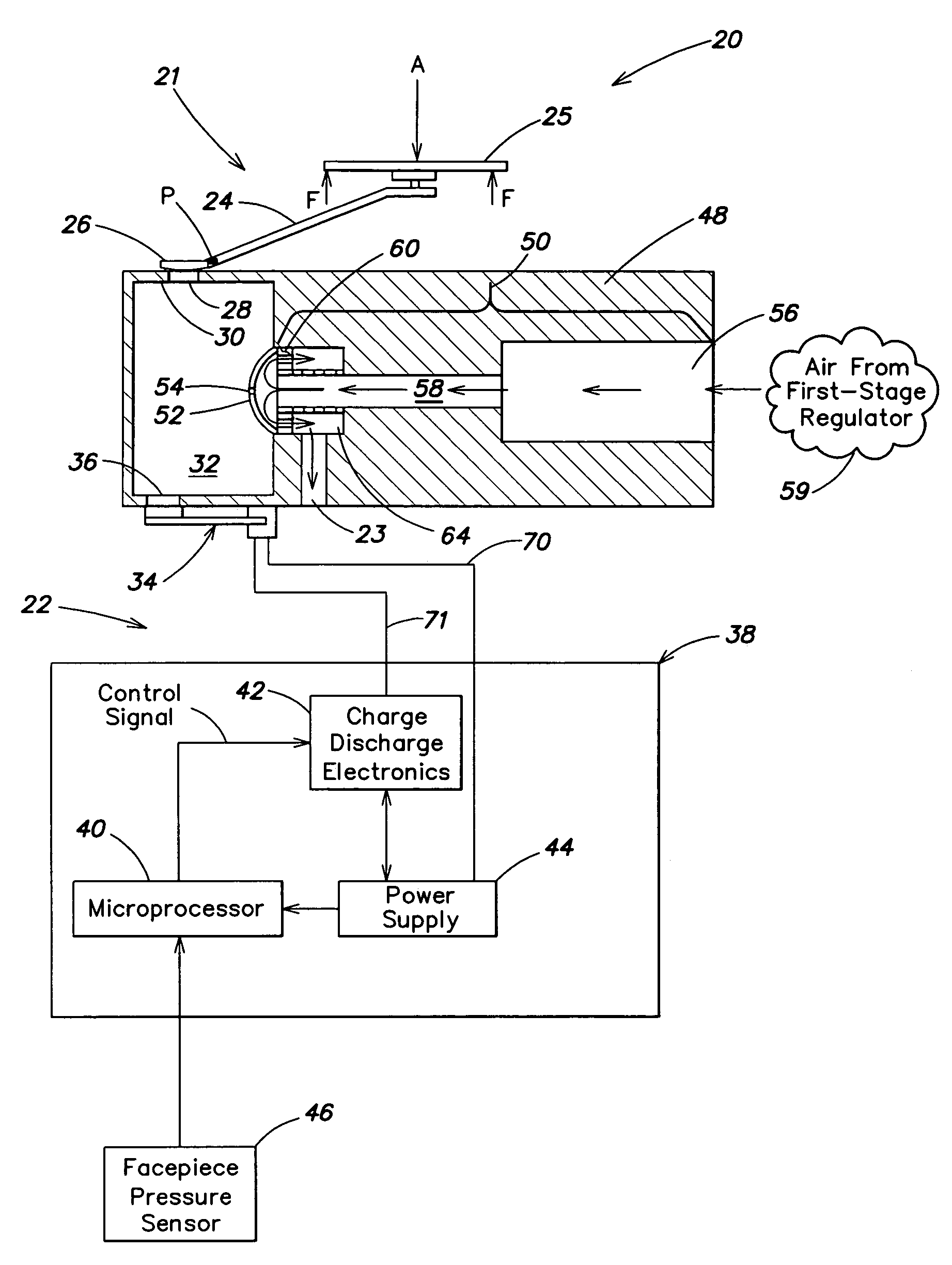
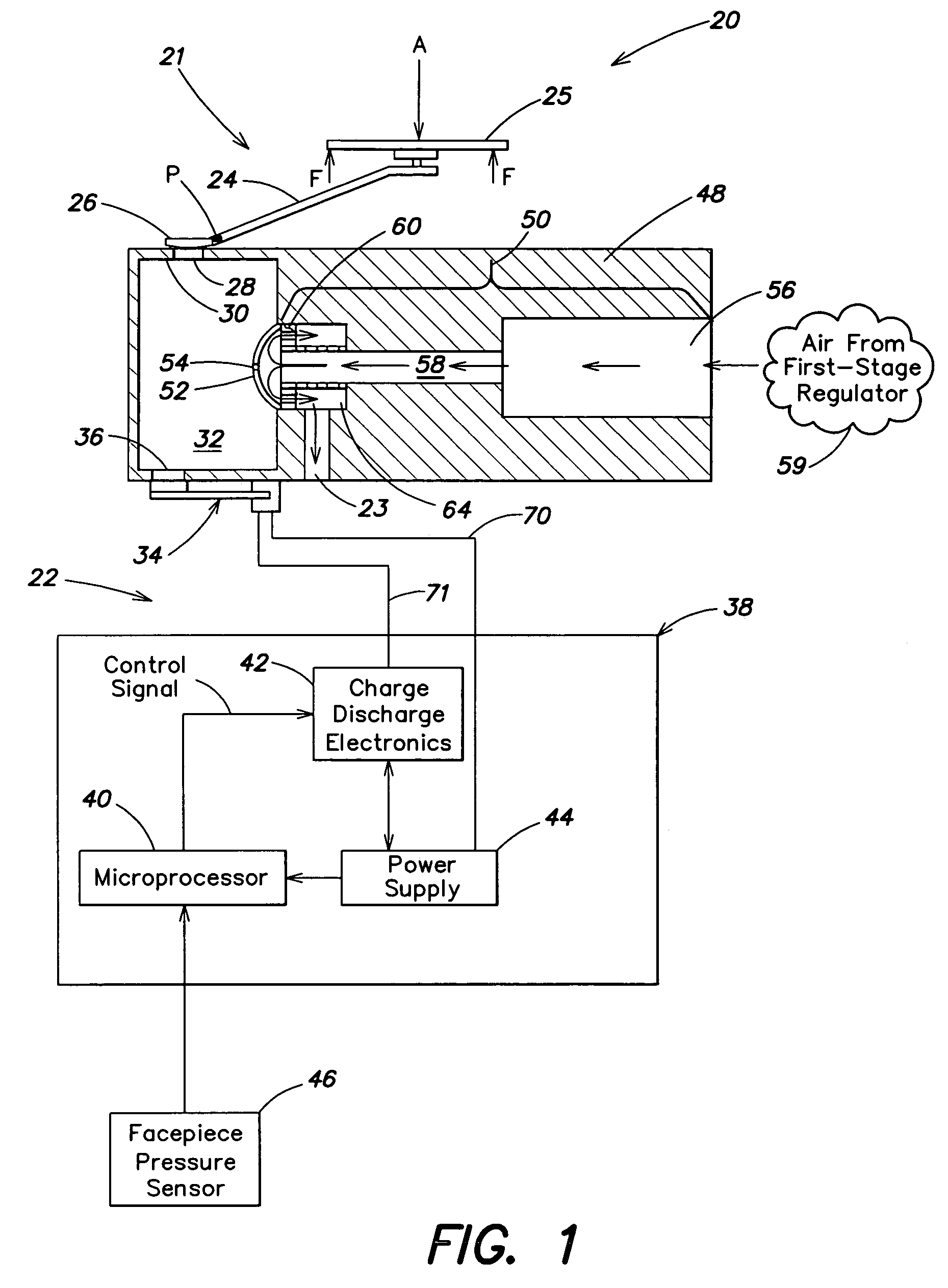
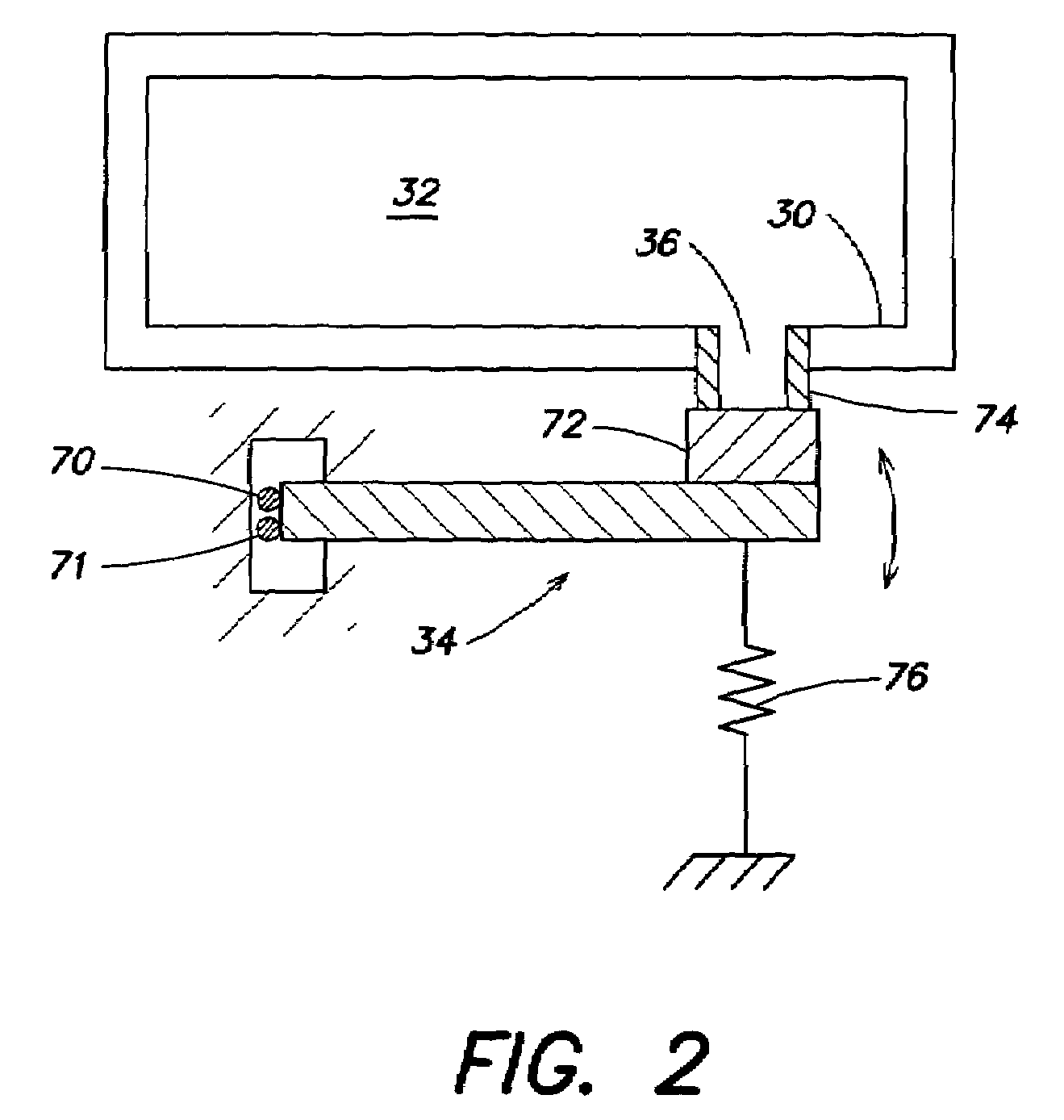
[0020]The present invention is directed to an electromechanically-assisted and an all-electronic control system for use in a second-stage regulator. The present invention includes a regulator control assembly, a method of using the assembly, and a method of adding the assembly to prior art regulators. Examples of the disclosed invention are depicted in FIGS. 1–6, although it should be understood that the present invention is not limited to this (or any other) particular embodiment, but rather is intended to cover all assemblies and methods that fairly fall within the broad scope of the appended claims.

[0021]Referring now to the drawings, FIG. 1 is a cross-sectional and partially schematic diagram of a regulator control assembly 20 for use in a SCBA second-stage regulator (not shown). Regulator control assembly 20, includes both mechanical actuator sub-assembly 21 and electromechanical actuator (EMA) sub-assembly 22 for controlling airflow through a single air supply line 23 that lea...


PUM


Abstract

An electromechanically-assisted control system for use in a second-stage regulator. Regulator control assembly (20), also referred to as EMA assembly (20), includes a mechanical actuator sub-assembly (21) and an electromechanical actuator (EMA) sub-assembly (22) for controlling airflow through single air supply line (23). EMA sub-assembly (22) includes electronically controllable actuator (ECA) (34), which removably seals EMA orifice (36) in wall (30) of pilot chamber (32). ECA (34) is electrically connected with and controlled by control electronics (38). The control electronics include programmable microprocessor (40), which is electrically connected with charge and discharge electronics (42), both of which are electrically connected with power supply (44). Alternatively, regulator control assembly (20′), also referred to as all-electronic (AE) assembly (20′), has only an EMA sub-assembly and no mechanical actuator sub-assembly. AE assembly (20′) does not include a low-pressure diaphragm, a lever arm, a first valve, or a pilot jet orifice.

Description

STATEMENT OF GOVERNMENT RIGHTS[0001]This invention was made with Government support under Grant No. 2 R44 HL58284-02 awarded by the National Heart, Lung and Blood Institute. The Government may have certain rights in the invention.FIELD OF THE INVENTION[0002]The present invention is generally related to the field of second-stage regulators for use in a self-contained breathing apparatus (SCBA). More particularly, the present invention is directed to an electromechanically-assisted control assembly for use in a second-stage regulator.BACKGROUND OF THE INVENTION[0003]There are millions of SCBA users in the United States alone, including firefighters, rescue workers, and hazardous materials workers. SCBAs are worn in hazardous environments over 100 million times each year. SCBAs provide clean breathing air on demand and maintain a positive pressure in the facepiece, protecting the user from toxic gases and aerosols in the environment.[0004]Prior art SCBA regulators can be slow to respon...

Claims


Application Information

Patent Timeline
IPC IPC(8): G05D16/20A62B18/10
CPCA62B18/10G05D16/2086Y10S137/908G05D16/2095Y10T137/7761Y10T137/0396
Inventor IZENSON, MICHAEL G.MAGARI, PATRICK J.
Owner CREARE INC
Why Eureka
Try Eureka