Sealed containers and methods of making and filling same

a container and seal technology, applied in the field of sealable containers, can solve the problems of infusible vulcanized rubber, high process and equipment costs, and time-consuming filling process, and achieve the effect of facilitating the handling of the vial and preventing accidental use of needle sticks

Inactive Publication Date: 2006-09-05
MEDINSTILL DEV
View PDF111 Cites 123 Cited by
  • Summary
  • Abstract
  • Description
  • Claims
  • Application Information

AI Technical Summary

Benefits of technology

[0015]In one embodiment of the present invention, the stopper includes a heat resealable portion overlying a substantially infusible portion. In another embodiment of the present invention, the stopper is a thermoplastic stopper defining a needle penetration region that is pierceable with a needle to form a needle aperture therethrough, and is heat resealable to hermetically seal the needle aperture by applying laser radiation at a predetermined wavelength and power thereto. The stopper comprises a thermoplastic body defining (i) a predetermined wall thickness in an axial direction thereof, (ii) a predetermined color and opacity that substantially absorbs the laser radiation at the predetermined wavelength and substantially prevents the passage of the radiation through the predetermined wall thickness thereof, and (iii) a predetermined color and opacity that causes the laser radiation at the predetermined wavelength and power to hermetically seal a needle aperture formed in the needle penetration region thereof in a predetermined time period of less than approximately 2 seconds and substantially without burning the needle penetration region.
[0025]One advantage of the preferred embodiments of the present invention is that the vial defines a diabolo or spool-like shape, thus facilitating the prevention of accidental needle sticks during use and otherwise facilitating handling of the vial during filling and other processing. Another advantage of certain preferred embodiments of the present invention is that the stopper and vial may be assembled without human intervention and prior to filling to thereby form hermetically sealed, empty vials that may be sterilized and maintained in the sterilized condition prior to filling. Yet another advantage of certain preferred embodiments of the present invention is that the plastic or like tamper-resistant portion allows the empty vials to be sterilized, such as by the application of gamma, e-beam or other radiation thereto.

Problems solved by technology

Vulcanized rubber, however, is infusible, and therefore any needle holes in such caps are not heat-resealable.
One of the drawbacks associated with such prior art vials, and processes and equipment for filling such vials, is that the filling process is time consuming, and the processes and equipment are expensive.
Further, the relatively complex nature of the filling processes and equipment can lead to more defectively filled vials than otherwise desired.
In many cases, there are complex assembly machines for assembling the vials or other containers that are located within the aseptic area of the filling machine that must be maintained sterile.
This type of machinery can be a significant source of unwanted particles.
In closed barrier systems, convection flow is inevitable and thus laminar flow, or substantially laminar flow, cannot be achieved.
When operation of an isolator is stopped, a media fill test may have to be performed which can last for several, if not many days, and can lead to repeated interruptions and significant reductions in production output for the pharmaceutical or other product manufacturer that is using the equipment.
In order to address such production issues, government-imposed regulations are becoming increasingly sophisticated and are further increasing the cost of already-expensive isolators and like filling equipment.
On the other hand, governmental price controls for injectables and vaccines, including, for example, preventative medicines, discourage such major financial investments.
One problem encountered with this approach, however, is that when the needle or like injection member is inserted through the stopper and then withdrawn, it leaves a tiny hole in the stopper.
However, the hole typically is not small enough to prevent air or other gases from passing through the hole and into the vial, and therefore such holes can allow the medicament to become contaminated or spoiled.
Certain preservatives, however, have been determined to cause undesirable effects on patients.
These preservative-free medicaments, and particularly preservative-free vaccines, are subject to contamination and / or spoilage if contained within a vial wherein the stopper has a needle hole as described above.
As noted above, it is difficult to maintain the sterility of stoppers and vials during the transportation, storage and assembly process.
Although crimped metal rings provide a mechanism for ensuring that the vial has not been compromised, the metal ring does not allow the vial assembly to be easily sterilized as a unit by using a gamma sterilization technique or similar process.
A metal ring complicates the gamma sterilization process.
Due to the density of the material, shadows (i.e., areas where the gamma radiation is prevented from passing through the material) are created which reduces the assurance that the interior storage cavity has been completely sterilized.
Also, the handling of the metal rings during the assembly process can create dust and / or other particulates that can contaminate the clean environment established for vial assembly and filling.
Additionally, the shape of conventional medicament vials can be disadvantageous from a safety and / or handling perspective.
If the needle slips off of the cap due, for example, to the relative placement of the fingers with respect to the cap, the healthcare worker's fingers are positioned in the slip path of the needle and therefore are likely to be pierced, causing a variety of safety concerns.
In addition, such conventional vials have a relatively high center of gravity making them prone to tipping during handling, and further, define shapes and / or configurations that are not always well suited for needle filling and / or automated handling in such needle filling and laser or other thermal resealing machines.

Method used


Image

  • Sealed containers and methods of making and filling same
  • Sealed containers and methods of making and filling same
  • Sealed containers and methods of making and filling same

Examples


Embodiment Construction

[0084]Reference is now made to the accompanying figures for the purpose of describing, in detail, preferred embodiments of the present disclosure. The figures and accompanying detailed description are provided as examples of the disclosed subject matter and are not intended to limit the scope thereof.

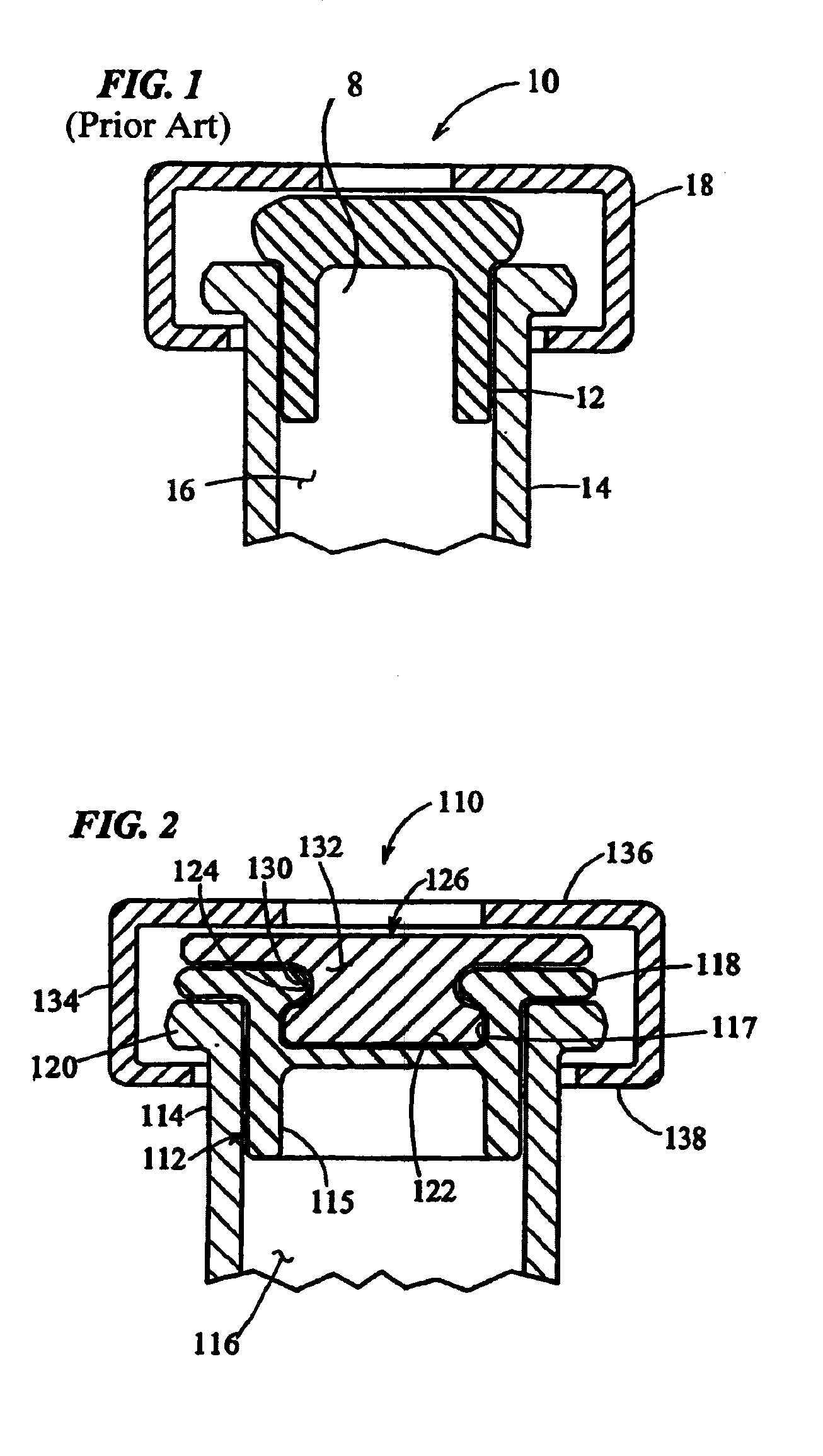
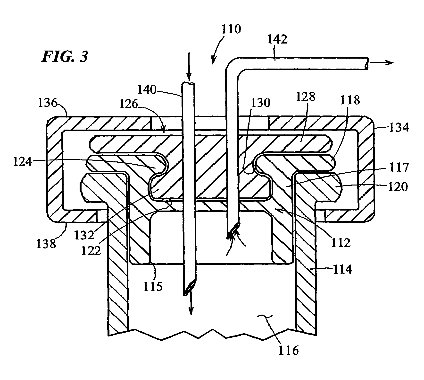
[0085]Turning to FIG. 2, a heat-resealable cap or stopper that may be used in the vials of the present invention is indicated generally by the reference numeral 110. The cap 110 includes a resilient base 112 made of vulcanized rubber or like material which is known to those of ordinary skill in the pertinent art, and acceptable for use in the manufacture of end caps or the portions thereof placed in contact with, or otherwise exposed to medicaments or other substances to be contained in the vials, such as vaccines. The base 112 defines a lower peripheral wall 115 shaped and dimensioned to be slidably received within the open end of a vial 114. The vial 114 may be made of any of numerous...


PUM

PropertyMeasurementUnit
wavelengthaaaaaaaaaa
poweraaaaaaaaaa
poweraaaaaaaaaa

Abstract

Disclosed is a uniquely configured medicament vial assembly which includes a storage vial, a stopper member and a securing ring. The vial assembly is configured to improve healthcare worker safety by providing a shielded gripping location to aid in the reduction of accidental needle sticks. The storage vial has a body portion which defines an interior chamber for storing a predetermined medicament and a neck portion through which medicament is received into and withdrawn from the interior chamber. The stopper member is inserted into the mouth of the vial and establishes a first seal. The securing ring is engaged with the mouth of the vial and adapted and configured for retaining the stopper member within the vial mouth and effectuating a second seal. The securing ring is formed from a thermoplastic and / or elastic material. Preferably, the securing ring is formed by molding the thermoplastic and / or elastic material over a portion of the storage vial and stopper member when engaged within the vial mouth.

Description

CROSS REFERENCE TO RELATED APPLICATIONS[0001]This application is a continuation-in-part of U.S. patent application Ser. No. 10 / 393,966, filed Mar. 21, 2003 now U.S. Pat. No. 6,684,916, entitled “Medicament Vial Having A Heat-Sealable Cap, And Apparatus and Method For Filling The Vial”, which is a divisional of similarly titled U.S. patent application Ser. No. 09 / 781,846, filed Feb. 12, 2001, now U.S. Pat. No. 6,604,561, issued Aug. 12, 2003, which, in turn, claims the benefit of similarly titled U.S. Provisional Application Ser. No. 60 / 182,139, filed on Feb. 11, 2000, and further, this application claims priority on U.S. Provisional Patent Application No. 60 / 408,068, filed Sep. 3, 2002, entitled “Sealed Containers And Methods Of Making And Filling Same”, each of which is hereby expressly incorporated by reference as part of the present disclosure.FIELD OF THE INVENTION[0002]The present invention relates to sealed containers, and more particularly, to containers, such as medicament v...

Claims


Application Information

Patent Timeline
Patent Type & Authority Patents(United States)
IPC IPC(8): B65B1/04A61J1/05A61J1/14A61J1/20A61J3/00B01L3/00B65B3/00B65B7/16B65DB65D51/00B67C3/00
CPCA61J1/1406B65D51/002A61J1/18B65B3/003B65B7/161A61J1/1412A61J1/2096A61J2001/1425A61J2001/1431A61J2001/1468A61J2001/201A61J2001/2013A61J2001/2055A61J2001/2075A61M2207/00A61M2209/045A61J1/201A61J1/2055A61J1/1425A61J1/2075A61J1/1431A61J1/1468A61J1/2013B65B2039/009B67C3/00B65B1/04B65B3/027B65B51/10B65B55/08
Inventor PY, DANIELASSION, NORBERT M.
Owner MEDINSTILL DEV
Why Eureka
Try Eureka